Toyota Tacoma (2015-2018) Service Manual: Open or Short in Rear Speed Sensor RH Circuit (C1407,C1408)
DESCRIPTION
Refer to DTCs C1401 and C1402 (See page .gif) ).
).
|
DTC Code |
DTC Detection Condition |
Trouble Area |
|---|---|---|
|
C1407 C1408 |
Either condition is met:
|
|
HINT:
- DTC C1407 is for the rear speed sensor RH.
- DTC C1408 is for the rear speed sensor LH.
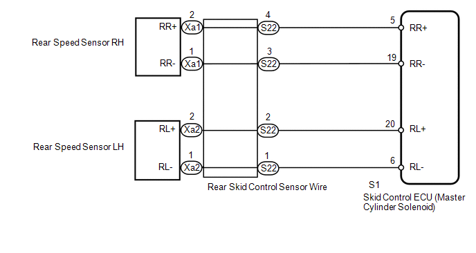
WIRING DIAGRAM
CAUTION / NOTICE / HINT
NOTICE:
- When replacing the skid control ECU (master cylinder solenoid), perform
calibration (See page
).
- Check the speed sensor signal after replacement (See page
).
PROCEDURE
|
1. |
CHECK HARNESS AND CONNECTOR (MOMENTARY INTERRUPTION) |
(a) Using the Techstream, check for any momentary interruption in the wire harness
and connector corresponding to the DTC (See page
).
|
Tester Display |
Measurement Item/Range |
Normal Condition |
Diagnostic Note |
|---|---|---|---|
|
RR Speed Open |
Rear speed sensor RH open detection/ Error or Normal |
Normal |
- |
|
RL Speed Open |
Rear speed sensor LH open detection/ Error or Normal |
Normal |
- |
OK:
Normal (there are no momentary interruptions).
HINT:
Perform the above inspection before removing the sensor and connector.
| NG | .gif) |
GO TO STEP 4 |
|
.gif)
|
2. |
READ VALUE USING TECHSTREAM (REAR SPEED SENSOR) |
| NG | |
GO TO STEP 4 |
|
|
3. |
RECONFIRM DTC |
(a) Clear the DTCs (See page
).
(b) Turn the ignition switch off.
(c) Start the engine.
(d) Drive the vehicle at a speed of 40 km/h (25 mph) or more for at least 60 seconds.
(e) Check if the same DTC is output (See page
).
|
Result |
Proceed to |
|---|---|
|
DTCs C1407 and C1408 are not output |
A |
|
DTCs C1407 and/or C1408 are output |
B |
| A | |
USE SIMULATION METHOD TO CHECK |
| B | |
REPLACE MASTER CYLINDER SOLENOID |
|
4. |
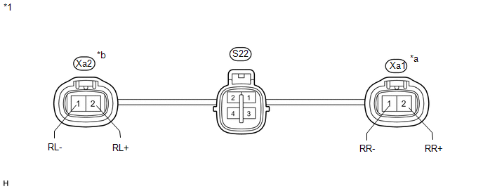
INSPECT SKID CONTROL SENSOR WIRE |
 Text in Illustration
|
*1 |
Skid Control Sensor Wire |
- |
- |
|
*a |
RH |
*b |
LH |
(a) Remove the skid control sensor wire.
(b) Measure the resistance according to the value(s) in the table below.
Standard Resistance:
RH|
Tester Connection |
Condition |
Specified Condition |
|---|---|---|
|
S22-4 - Xa1-2 (RR+) |
Always |
Below 1 Ω |
|
S22-3 - Xa1-1 (RR-) |
Always |
Below 1 Ω |
|
S22-4 - S22-3 |
Always |
10 kΩ or higher |
|
S22-4 - S22-1 |
Always |
10 kΩ or higher |
|
S22-4 - S22-2 |
Always |
10 kΩ or higher |
|
Tester Connection |
Condition |
Specified Condition |
|---|---|---|
|
S22-2 - Xa2-2 (RL+) |
Always |
Below 1 Ω |
|
S22-1 - Xa2-1 (RL-) |
Always |
Below 1 Ω |
|
S22-2 - S22-1 |
Always |
10 kΩ or higher |
|
S22-2 - S22-3 |
Always |
10 kΩ or higher |
|
S22-2 - S22-4 |
Always |
10 kΩ or higher |
| NG | |
REPLACE SKID CONTROL SENSOR WIRE |
|
|
5. |
CHECK HARNESS AND CONNECTOR (SKID CONTROL ECU - REAR SPEED SENSOR) |
(a) Install the skid control sensor wire.
(b) Disconnect the S1 skid control ECU (master cylinder solenoid) connector.
(c) Disconnect the Xa1 and/or Xa2 rear speed sensor connector.
(d) Measure the resistance according to the value(s) in the table below.
Standard Resistance:
RH|
Tester Connection |
Condition |
Specified Condition |
|---|---|---|
|
S1-5 (RR+) - Xa1-2 (RR+) |
Always |
Below 1 Ω |
|
S1-5 (RR+) - Body ground |
Always |
10 kΩ or higher |
|
S1-19 (RR-) - Xa1-1 (RR-) |
Always |
Below 1 Ω |
|
S1-19 (RR-) - Body ground |
Always |
10 kΩ or higher |
|
Tester Connection |
Condition |
Specified Condition |
|---|---|---|
|
S1-20 (RL+) - Xa2-2 (RL+) |
Always |
Below 1 Ω |
|
S1-20 (RL+) - Body ground |
Always |
10 kΩ or higher |
|
S1-6 (RL-) - Xa2-1 (RL-) |
Always |
Below 1 Ω |
|
S1-6 (RL-) - Body ground |
Always |
10 kΩ or higher |
| NG | |
REPAIR OR REPLACE HARNESS OR CONNECTOR |
|
|
6. |
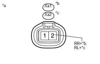
INSPECT SKID CONTROL ECU (RR+, RL+ TERMINAL) |
(a) Disconnect the Xa1 and/or Xa2 rear speed sensor connector.
(b) Connect the S1 skid control ECU (master cylinder solenoid) connector.
|
(c) Measure the voltage according to the value(s) in the table below. Standard Voltage: RH
|
|
| OK | |
REPLACE REAR SPEED SENSOR |
| NG | |
REPLACE MASTER CYLINDER SOLENOID |
 Open or Short in Front Speed Sensor RH Circuit (C1405,C1406)
DESCRIPTION
Refer to DTCs C1401 and C1402 (See page ).
DTC Code
DTC Detection Condition
Trouble Area
C1405
C1406
Either condition is ...
 Front Speed Sensor RH Performance (C1409,C1410)
DESCRIPTION
Refer to DTCs C1401 and C1402 (See page ).
DTC Code
DTC Detection Condition
Trouble Area
C1409
C1410
One of the following ...
Other materials:
Inspection
INSPECTION
PROCEDURE
1. INSPECT INPUT SHAFT
(a) Using a dial indicator and 2 V-blocks, measure the shaft runout.
Maximum runout:
0.03 mm (0.0012 in.)
If the runout is more than the maximum, replace the input shaft.
HINT:
Measure the 3 areas shown in the illustration wit ...
Display does not Dim when Light Control Switch is Turned ON
PROCEDURE
1.
CHECK IMAGE QUALITY SETTING
(a) Display the "Display Settings" screen.
(b) Turn the light control switch to the tail or head position.
(c) Check if "Day Mode" on the display adjustment screen is on.
OK:
"Day Mode" sett ...
Main Body ECU Vehicle Information Reading/Writing Process Malfunction (B15F6)
DESCRIPTION
This DTC is stored when items controlled by the main body ECU (multiplex network
body ECU) cannot be customized via the audio and visual system vehicle customization
screen.
HINT:
The main body ECU (multiplex network body ECU) controls the items for the following
systems th ...
