Toyota Tacoma (2015-2018) Service Manual: Parts Location
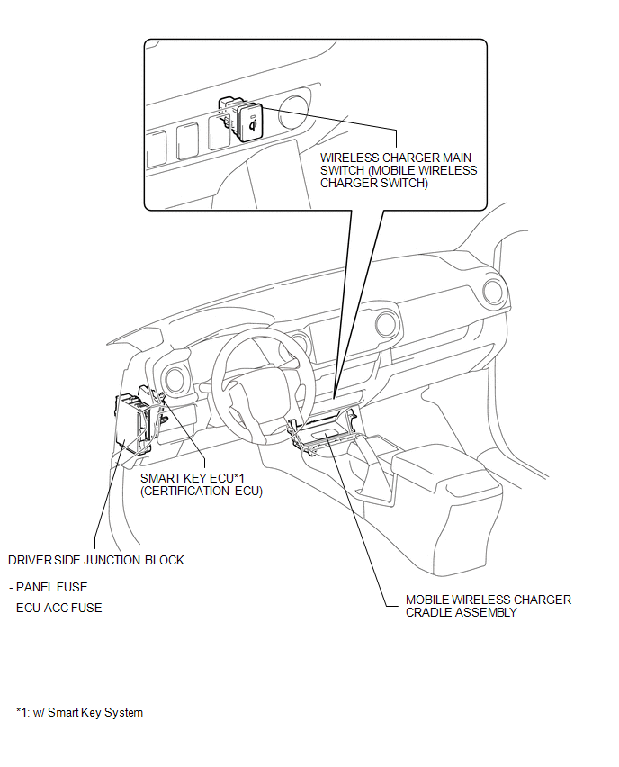
PARTS LOCATION
ILLUSTRATION
 Precaution
PRECAUTION
1. IGNITION SWITCH EXPRESSIONS
(a) The type of ignition switch used on this model differs according to the specifications
of the vehicle. The expressions listed in the table below are u ...
 System Description
SYSTEM DESCRIPTION
1. WIRELESS CHARGER FUNCTION OUTLINE
(a) The wireless charging system enables Qi-compliant* rechargeable devices,
such as a cellular phone, to be recharged by merely placing it ...
Other materials:
Freeze Frame Data
FREEZE FRAME DATA
1. DESCRIPTION
The ECM records vehicle and driving condition information as freeze frame data
the moment a DTC is stored. When troubleshooting, freeze frame data can be helpful
in determining whether the vehicle was moving or stationary, whether the engine
was warmed up or ...
Bottle holders
Front
Front console box (Separated type
front seat)
Rear (Double Cab models)
■Bottle holders
Depending on their size or shape, some bottles may not fit in the holders.
NOTICE
■Items that should not be stowed in the bottle holders
Put the cap on before stowing a bottle. Do ...
Installation
INSTALLATION
CAUTION / NOTICE / HINT
HINT:
Use the same procedure for both the RH and LH sides.
The procedure described below is for the LH side.
PROCEDURE
1. INSTALL FRONT SHOULDER BELT ANCHOR ADJUSTER ASSEMBLY
(a) As shown in the illustration, engage the 2 guides ...
