Toyota Tacoma (2015-2018) Service Manual: Reservoir Level Switch Disconnected (C1453,C1454)
DESCRIPTION
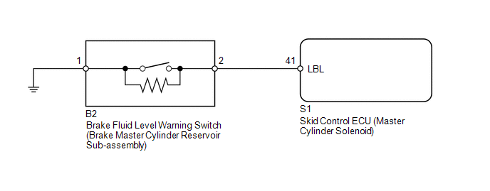
The brake fluid level warning switch sends the appropriate signal to the skid control ECU (master cylinder solenoid) when the brake fluid level drops.
|
DTC Code |
DTC Detection Condition |
Trouble Area |
|---|---|---|
|
C1453 |
With the ECU terminal IG1 voltage at 10 to 14 V, an open in the brake fluid level warning switch circuit continues for 2 seconds or more. |
|
|
C1454 |
The fluid level of the reservoir is LOW for 40 seconds after the ignition switch is turned to ON, or for 7 seconds during pump motor operation. |
WIRING DIAGRAM
CAUTION / NOTICE / HINT
NOTICE:
When replacing the skid control ECU (master cylinder solenoid), perform calibration
(See page .gif) ).
).
PROCEDURE
|
1. |
CHECK BRAKE FLUID LEVEL |
(a) Turn the ignition switch off.
(b) Depress the brake pedal 40 times or more (until the pedal reaction feels light and pedal stroke becomes longer).
(c) Check the amount of fluid in the brake reservoir.
HINT:
When the ignition switch is turned to ON, brake fluid is sent to the accumulator and the fluid level decreases by approximately 5 mm (0.197 in.) from the level when the ignition switch is off (normal).
OK:
Brake fluid level is normal.
| NG | .gif) |
CHECK AND REPAIR BRAKE FLUID LEAKAGE |
|
.gif)
|
2. |
INSPECT BRAKE FLUID LEVEL WARNING SWITCH |
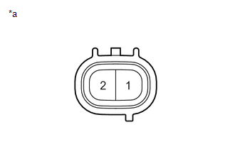
(a) Disconnect the B2 brake fluid level warning switch (brake master cylinder reservoir sub-assembly) connector.
|
(b) Measure the resistance according to the value(s) in the table below. HINT: A float is placed inside the reservoir. Its position can be changed by increasing/decreasing the level of brake fluid. Standard Resistance:
HINT: If there is no problem after finishing the above check, adjust the brake fluid level to the MAX level. |
|
| NG | |
REPLACE BRAKE MASTER CYLINDER RESERVOIR SUB-ASSEMBLY |
|
|
3. |
CHECK HARNESS AND CONNECTOR (SKID CONTROL ECU - BRAKE FLUID LEVEL WARNING SWITCH) |
(a) Disconnect the S1 skid control ECU (master cylinder solenoid) connector.
(b) Disconnect the B2 brake fluid level warning switch (brake master cylinder reservoir sub-assembly) connector.
(c) Measure the resistance according to the value(s) in the table below.
Standard Resistance:
|
Tester Connection |
Condition |
Specified Condition |
|---|---|---|
|
S1-41 (LBL) - B2-2 |
Always |
Below 1 Ω |
|
S1-41 (LBL) - Body ground |
Always |
10 kΩ or higher |
|
S1-41 (GND) - Body ground |
Always |
Below 1 Ω |
| NG | |
REPAIR OR REPLACE HARNESS OR CONNECTOR |
|
|
4. |
RECONFIRM DTC |
(a) Clear the DTCs (See page
).
(b) Turn the ignition switch off.
(c) Start the engine and idle it for approximately 40 seconds.
(d) Check if the same DTCs are output (See page
).
|
Result |
Proceed to |
|---|---|
|
DTC is output |
A |
|
DTC is not output |
B |
| A | |
REPLACE MASTER CYLINDER SOLENOID |
| B | |
USE SIMULATION METHOD TO CHECK |
 Master Cylinder Pressure Sensor Zero Point High Malfunction (C1422,C1456)
DESCRIPTION
Refer to DTCs C1421, C1423, C1424, C1455, C1457 and C1458 (See page
).
DTC Code
DTC Detection Condition
Trouble Area
C1422
...
 ABS Warning Light does not Come ON
DESCRIPTION
Refer to ABS Warning Light Remains ON (See page
).
WIRING DIAGRAM
Refer to ABS Warning Light Remains ON (See page
).
CAUTION / NOTICE / HINT
NOTICE:
When replacing the sk ...
Other materials:
Inspection
INSPECTION
PROCEDURE
1. INSPECT OIL CLEARANCE
(a) Using a micrometer and caliper gauge, measure the oil seal clearance.
Standard clearance:
0.021 to 0.043 mm (0.0008 to 0.0017 in.)
Maximum clearance:
0.07 mm (0.0028 in.)
If it is greater than the maximum, replace the vane pump assembly.
...
Main Body ECU Vehicle Information Reading/Writing Process Malfunction (B15F6)
DESCRIPTION
This DTC is stored when items controlled by the main body ECU (multiplex network
body ECU) cannot be customized via the audio and visual system vehicle customization
screen.
HINT:
The main body ECU (multiplex network body ECU) controls the items for the following
systems th ...
Steering Angle Sensor Power Source Voltage Malfunction (C1432)
DESCRIPTION
Steering angle sensor (spiral cable with sensor sub-assembly) signals are sent
to the skid control ECU (master cylinder solenoid) via the CAN communication system.
When there is a malfunction in the CAN communication system, it is detected by the
steering angle sensor zero point m ...
