Toyota Tacoma (2015-2018) Service Manual: Rear Cross Traffic Alert Buzzer
Components
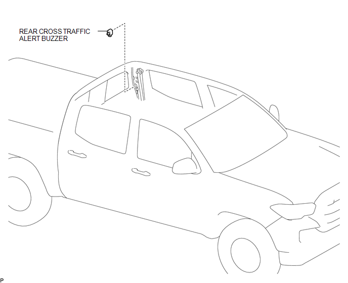
COMPONENTS
ILLUSTRATION
Installation
INSTALLATION
PROCEDURE
1. INSTALL REAR CROSS TRAFFIC ALERT BUZZER
(a) Engage the clamp to install the rear cross traffic alert buzzer.
(b) Connect the connector.
2. INSTALL QUARTER INSIDE TRIM BOARD LH (for Double Cab)
(See page .gif) )
)
3. INSTALL QUARTER INSIDE TRIM BOARD LH (for Access Cab)
(See page )
Removal
REMOVAL
PROCEDURE
1. REMOVE QUARTER INSIDE TRIM BOARD LH (for Double Cab)
(See page .gif) )
)
2. REMOVE QUARTER INSIDE TRIM BOARD LH (for Access Cab)
(See page )
3. REMOVE REAR CROSS TRAFFIC ALERT BUZZER
|
(a) Disconnect the connector. |
|
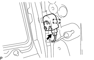
(b) Disengage the clamp to remove the rear cross traffic alert buzzer.
 Clearance Warning ECU Power Source Circuit
DESCRIPTION
This circuit provides power to operate the clearance warning ECU assembly.
WIRING DIAGRAM
CAUTION / NOTICE / HINT
NOTICE:
Inspect the fuse for circuits related to this system before ...

Other materials:
Installation
INSTALLATION
PROCEDURE
1. ADJUST COMPRESSOR OIL
(a) for HFC-134a (R134a):
(1) When replacing the compressor and magnetic clutch with new ones, after gradually
discharging the refrigerant gas from the service valve, drain the following volume
of oil from new compressor and magnetic clutch bef ...
Removal
REMOVAL
PROCEDURE
1. REMOVE ENGINE ASSEMBLY
(See page )
2. REMOVE IGNITION COIL ASSEMBLY
3. REMOVE ENGINE OIL LEVEL DIPSTICK GUIDE
4. REMOVE CAMSHAFT TIMING OIL CONTROL SOLENOID ASSEMBLY (for Intake Side of Bank
1)
5. REMOVE CAMSHAFT TIMING OIL CONTROL SOLENOID ASSEMBLY (for Exha ...
Front Radar Sensor Region Code Mismatch (C1A0A)
DESCRIPTION
The forward recognition camera receives necessary information from the millimeter
wave radar sensor assembly.
When the forward recognition camera judges that a millimeter wave radar sensor
assembly which is not compatible with the vehicle has been installed, DTC C1A0A
is stored.
...
