Toyota Tacoma (2015-2018) Service Manual: Parts Location
PARTS LOCATION
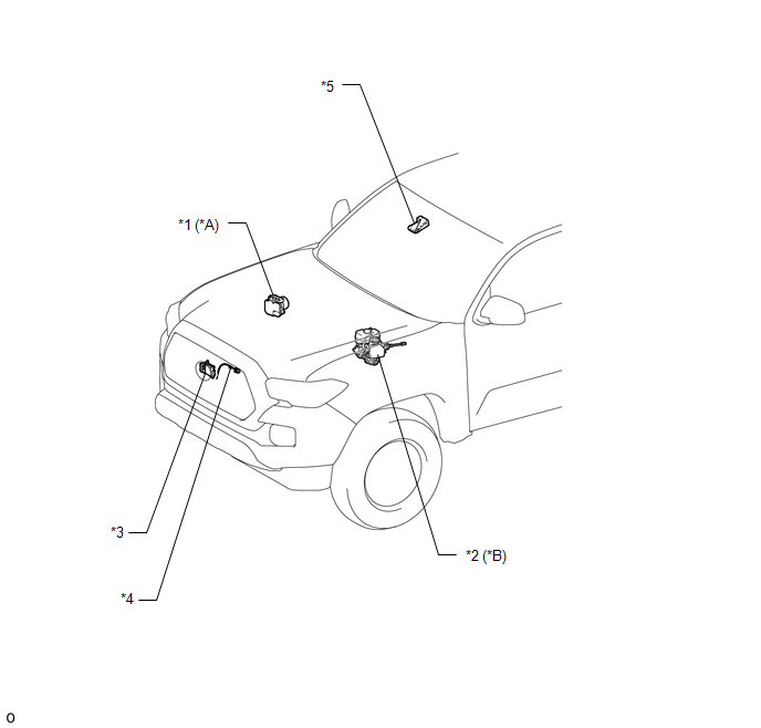
ILLUSTRATION
|
*A |
for Vacuum Brake Booster |
*B |
for Hydraulic Brake Booster |
|
*1 |
SKID CONTROL ECU (BRAKE ACTUATOR ASSEMBLY) |
*2 |
SKID CONTROL ECU (MASTER CYLINDER SOLENOID) |
|
*3 |
MILLIMETER WAVE RADAR SENSOR ASSEMBLY |
*4 |
MILLIMETER WAVE RADAR WIRE |
|
*5 |
FORWARD RECOGNITION CAMERA |
- |
- |
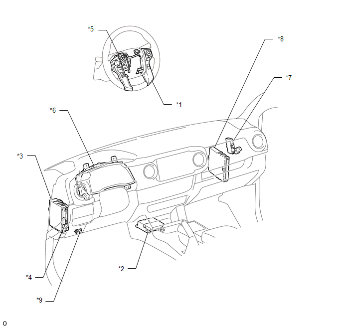
ILLUSTRATION
|
*1 |
STEERING PAD SWITCH ASSEMBLY - LANE DEPARTURE ALERT MAIN SWITCH - CUSTOMIZE SWITCH |
*2 |
YAW RATE AND ACCELERATION SENSOR (AIRBAG SENSOR ASSEMBLY) |
|
*3 |
DRIVER SIDE JUNCTION BLOCK - IG1 NO. 2 FUSE - ECU-IG NO. 2 FUSE |
*4 |
MAIN BODY ECU (MULTIPLEX NETWORK BODY ECU) |
|
*5 |
SPIRAL CABLE WITH SENSOR SUB-ASSEMBLY |
*6 |
COMBINATION METER ASSEMBLY |
|
*7 |
NETWORK GATEWAY ECU |
*8 |
ECM |
|
*9 |
DLC3 |
- |
- |
 Precaution
PRECAUTION
PRECAUTION FOR DISCONNECTING CABLE FROM NEGATIVE BATTERY TERMINAL
NOTICE:
When disconnecting the cable from the negative (-) battery terminal, initialize
the following systems after th ...
 System Description
SYSTEM DESCRIPTION
LANE DEPARTURE ALERT SYSTEM DESCRIPTION
(a) The lane departure alert system is a system which uses the forward recognition
camera to recognize and determine the lane and the pos ...
Other materials:
Terminals Of Ecu
TERMINALS OF ECU
1. ECM
Terminal No. (Symbol)
Wiring Color
Terminal Description
Condition
Specified Condition
E14-20 (TC) - E11-1 (E1)
G - W-B
DTC output signal
Ignition switch ON
...
Dtc Check / Clear
DTC CHECK / CLEAR
1. CHECK DTC (for TIRE PRESSURE WARNING ECU AND RECEIVER) (USING TECHSTREAM)
(a) Turn the ignition switch off.
(b) Connect the Techstream to the DLC3.
(c) Turn the ignition switch to ON.
(d) Turn the Techstream on.
(e) Enter the following menus: Chassis / Tire Pressure Monito ...
Installation
INSTALLATION
PROCEDURE
1. INSTALL WINDSHIELD WIPER MOTOR ASSEMBLY
(a) Apply MP grease to the crank arm pivot of the windshield wiper motor
assembly.
Text in Illustration
*1
Crank Arm Pivot
...
