Toyota Tacoma (2015-2018) Service Manual: Reassembly
REASSEMBLY
PROCEDURE
1. INSTALL OIL PUMP COVER
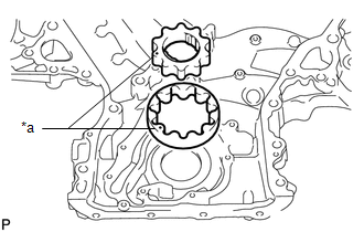
(a) Apply fresh engine oil to the drive and driven rotors.
|
(b) Place the drive and driven rotors into the timing chain cover assembly with the marks facing the oil pump cover side. Text in Illustration
|
|
|
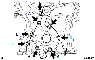
(c) Install the oil pump cover with the 8 bolts. Torque: 9.1 N·m {92 kgf·cm, 81 in·lbf} Bolt Length:
|
|
2. INSTALL OIL PUMP RELIEF VALVE
(a) Coat the oil pump relief valve with engine oil.
(b) Insert the oil pump relief valve and oil pump relief valve spring into the oil pump cover hole.
(c) Using a 27 mm socket wrench, install the oil pump relief valve plug.
Torque:
49 N·m {500 kgf·cm, 36 ft·lbf}
 Installation
INSTALLATION
PROCEDURE
1. INSTALL FRONT CRANKSHAFT OIL SEAL
(a) Using SST and a hammer, tap in a new oil seal until its surface is
flush with the timing chain cover assembly edge.
...
 2gr-fks Starting
...
Other materials:
Steering Pad Switch
Components
COMPONENTS
ILLUSTRATION
*1
STEERING PAD SWITCH ASSEMBLY
-
-
Removal
REMOVAL
PROCEDURE
1. REMOVE STEERING PAD
(See page )
2. REMOVE STEERING PAD SWITCH ASSEMBLY
(a) Disconnect the 2 connectors.
...
Inspection
INSPECTION
PROCEDURE
1. INSPECT FRONT SEATBACK HEATER ASSEMBLY
(a) Check the operation of the front seatback heater assembly.
(1) Apply battery voltage and check the operation of the front seatback
heater assembly.
OK:
Connection
Conditio ...
Pressure Control Solenoid "D" Circuit Open (P271313)
DESCRIPTION
Refer to the system description for DTC P27137F (See page
).
DTC No.
DTC Detection Condition
Trouble Area
SAE
P271313
Open or short is detected in shift solenoid valve SLT circuit for 1 second
or more while d ...
