Toyota Tacoma (2015-2018) Service Manual: On-vehicle Inspection
ON-VEHICLE INSPECTION
PROCEDURE
1. INSPECT FRONT AXLE HUB BEARING
(a) Remove the front wheel.
(b) for 4WD:
(1) Remove the front axle hub grease cap (See page
.gif) ).
).
(c) Remove the front disc brake caliper (See page
).
(d) Remove the front disc.
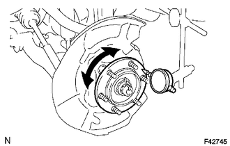
(e) Inspect the axle hub backlash.
(1) Using a dial indicator, check the backlash near the center of the axle hub.
Maximum:
0.05 mm (0.0020 in.)
If the backlash exceeds the maximum, replace the bearing.
|
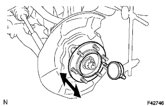
(f) Inspect the axle hub deviation. (1) Using a dial indicator, check the distortion of the surface of the axle hub. Maximum: 0.05 mm (0.0020 in.) If the deviation exceeds the maximum, replace the bearing. |
|
2. INSPECT REAR AXLE HUB BEARING
(a) Remove the rear wheel.
(b) Remove the rear brake drum (See page ).
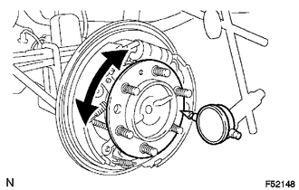
(c) Inspect the axle shaft backlash.
(1) Using a dial indicator, check the backlash near the center of the axle shaft.
Maximum:
0.05 mm (0.0020 in.)
If the backlash exceeds the maximum, replace the bearing.
|
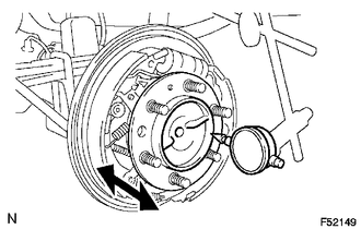
(d) Inspect the axle shaft deviation. (1) Using a dial indicator, check the distortion of the surface of the axle shaft. Maximum: 0.05 mm (0.0020 in.) If the deviation exceeds the maximum, replace the bearing. |
|
 Problem Symptoms Table
PROBLEM SYMPTOMS TABLE
HINT:
Use the table below to help determine the cause of problem symptoms. If multiple
suspected areas are listed, the potential causes of the symptoms are listed in order
...
 Front Axle Hub
...
Other materials:
Front Radar Sensor Region Code Mismatch (C1A0A)
DESCRIPTION
The forward recognition camera receives necessary information from the millimeter
wave radar sensor assembly.
When the forward recognition camera judges that a millimeter wave radar sensor
assembly which is not compatible with the vehicle has been installed, DTC C1A0A
is stored.
...
Freeze Frame Data
FREEZE FRAME DATA
CHECK FREEZE FRAME DATA
HINT:
The ECU records vehicle and driving condition information as freeze frame data
the moment a DTC is stored.
(a) Connect the Techstream to the DLC3.
(b) Turn the ignition switch to ON.
(c) Turn the Techstream on.
(d) Enter the following menus: P ...
Reassembly
REASSEMBLY
CAUTION / NOTICE / HINT
CAUTION:
Wear protective gloves. Sharp areas on the parts may injure your hands.
PROCEDURE
1. INSTALL SEPARATE TYPE REAR SEATBACK COVER
(a) Using hog ring pliers, install the separate type rear seatback cover
with 2 new hog rings.
Text in Il ...
