Toyota Tacoma (2015-2018) Service Manual: Radio Receiver Power Source Circuit
DESCRIPTION
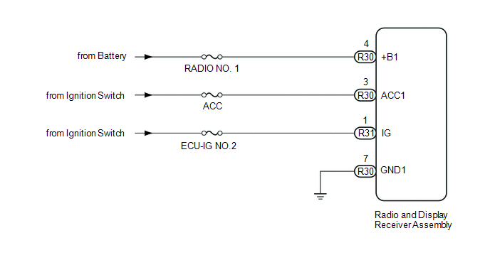
This is the power source circuit to operate the radio and display receiver assembly.
WIRING DIAGRAM
CAUTION / NOTICE / HINT
NOTICE:
- Inspect the fuses for circuits related to this system before performing the following inspection procedure.
PROCEDURE
|
1. |
CHECK HARNESS AND CONNECTOR (RADIO AND DISPLAY RECEIVER ASSEMBLY - BATTERY AND BODY GROUND) |
|
(a) Disconnect the radio and display receiver assembly connectors. |
|
(b) Measure the resistance according to the value(s) in the table below.
Standard Resistance:
|
Tester Connection |
Condition |
Specified Condition |
|---|---|---|
|
R30-7 (GND1) - Body ground |
Always |
Below 1 Ω |
(c) Measure the voltage according to the value(s) in the table below.
Standard Voltage:
|
Tester Connection |
Switch Condition |
Specified Condition |
|---|---|---|
|
R30-4 (+B1) - R30-7 (GND1) |
Always |
11 to 14 V |
|
R30-3 (ACC1) - R30-7 (GND1) |
Ignition switch ACC |
11 to 14 V |
|
R31-1 (IG) - R30-7 (GND1) |
Ignition switch ON |
11 to 14 V |
|
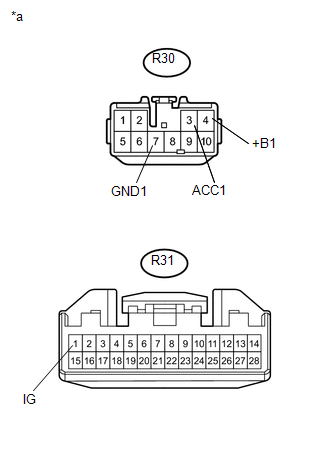
*a |
Front view of wire harness connector (to Radio and Display Receiver Assembly) |
| OK | .gif) |
PROCEED TO NEXT SUSPECTED AREA SHOWN IN PROBLEM SYMPTOMS TABLE |
| NG | |
REPAIR OR REPLACE HARNESS OR CONNECTOR |
 Microphone Circuit between Microphone and Radio Receiver
DESCRIPTION
The radio and display receiver assembly and telephone microphone assembly are
connected to each other using the microphone connection detection signal lines.
Using this circuit, the ra ...

Other materials:
Radio Receiver
Components
COMPONENTS
ILLUSTRATION
ILLUSTRATION
Removal
REMOVAL
PROCEDURE
1. REMOVE INSTRUMENT CLUSTER CENTER FINISH PANEL SUB-ASSEMBLY
(See page )
2. REMOVE RADIO AND DISPLAY RECEIVER ASSEMBLY WITH BRACKET
(a) Remove the 4 bolts.
...
Fail-safe Chart
FAIL-SAFE CHART
FAIL-SAFE FUNCTION
(a) When a malfunction occurs in the lane departure alert system, a message will
be displayed on the multi-information display in the combination meter assembly
and the lane departure alert system will be disabled depending on the malfunction.
War ...
On-vehicle Inspection
ON-VEHICLE INSPECTION
PROCEDURE
1. INSPECT RADIATOR CAP SUB-ASSEMBLY
CAUTION:
Do not remove the radiator cap sub-assembly while the engine and radiator assembly
are still hot. Pressurized, hot engine coolant and steam may be released and cause
serious burns.
(a) Measure the valve opening pr ...
