Toyota Tacoma (2015-2018) Service Manual: Operation Check
OPERATION CHECK
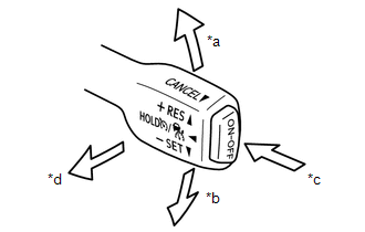
INPUT SIGNAL CHECK
|
*a |
+RES |
|
*b |
-SET |
|
*c |
ON-OFF |
|
*d |
CANCEL |
(a) Connect the Techstream to the DLC3.
(b) Check the cruise control main switch using the Data List function of the Techstream (ON-OFF, -SET, +RES and CANCEL).
Click here .gif)
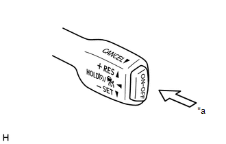
INSPECT CRUISE CONTROL MAIN SWITCH (ON-OFF BUTTON)
(a) Turn the ignition switch to ON.
(b) Turn the dynamic radar cruise control system on using the cruise control main switch (ON-OFF button).
|
*a |
ON-OFF |
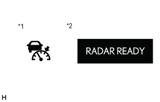
(c) Check that the cruise control indicator (vehicle-to-vehicle distance control mode) in the combination meter assembly illuminates and "RADAR READY" is displayed on the multi-information display.
|
*1 |
Cruise Control Indicator (Vehicle-to-vehicle Distance Control Mode) |
|
*2 |
Multi-information Display |
(d) Turn the cruise control system off using the cruise control main switch (ON-OFF button). Check that the cruise control indicator (vehicle-to-vehicle distance control mode) in the combination meter assembly and "RADAR READY" on the multi-information display turn off.
(e) Turn the ignition switch off with the cruise control indicator (vehicle-to-vehicle distance control mode) in the combination meter assembly illuminated and "RADAR READY" on the multi-information display displayed. Turn the ignition switch to ON and check the cruise control indicator (vehicle-to-vehicle distance control mode) in the combination meter assembly and "RADAR READY" on the multi-information display are turned off.
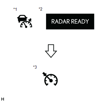
INSPECT MODE SELECT
(a) Turn the ignition switch to ON.
(b) Push and hold the cruise control main switch (ON-OFF button) for approximately 1.5 seconds. Check that the cruise control indicator (vehicle-to-vehicle distance control mode) in the combination meter assembly and "RADAR READY" on the multi-information display turn off and the cruise control indicator (constant speed control mode) illuminates.
|
*a |
ON-OFF |
(c) Check that the cruise control indicator (vehicle-to-vehicle distance control mode) turns off and the cruise control indicator (constant speed control mode) illuminates.
|
*1 |
Cruise Control Indicator (Vehicle-to-vehicle Distance Control Mode) |
|
*2 |
Multi-information Display |
|
*3 |
Cruise Control Indicator (Constant Speed Control Mode) |
NOTICE:
Do not push any other switches before pushing the cruise control main switch to MODE. If any other switch is pushed, turn the dynamic radar cruise control system off and repeat the procedure above.
HINT:
If a malfunction is detected, turn the ignition switch off and repeat the procedure above.
INSPECT STEERING PAD SWITCH ASSEMBLY
(a) Turn the ignition switch to ON.
(b) Turn the dynamic radar cruise control system on using the cruise control main switch (ON-OFF button).
|
*a |
ON-OFF |
(c) Press the steering pad switch assembly (distance control switch).
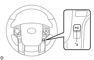
|
*a |
Distance Control Switch |
(d) Check that the indicator of the vehicle-to-vehicle distance, which is shown on the multi-information display in the combination meter assembly changes from long to middle to short in that order.
HINT:
Long is automatically selected each time the ignition switch to ON.
 System Description
SYSTEM DESCRIPTION
GENERAL
The cruise control main switch is used to turn the dynamic radar cruise control
system on and off, as well as operate 7 functions: SET, - (COAST), TAP-DOWN, RES
(RESUM ...
 Road Test
ROAD TEST
PROBLEM SYMPTOM CONFIRMATION
HINT:
The dynamic radar cruise control system has 2 cruise control modes:
constant speed control mode and vehicle-to-vehicle distance control mode ...
Other materials:
System Diagram
SYSTEM DIAGRAM
Transmitting ECU (Transmitter)
Receiving ECU
Signals
Communication Method
ECM
Skid control ECU
Throttle position signal
Engine speed signal
Accelerator pedal position ...
Problem Symptoms Table
PROBLEM SYMPTOMS TABLE
HINT:
Use the table below to help determine the cause of problem symptoms. If multiple
suspected areas are listed, the potential causes of the symptoms are listed in order
of probability in the "Suspected Area" column of the table. Check each symptom by
check ...
Reassembly
REASSEMBLY
PROCEDURE
1. INSTALL STARTER ARMATURE ASSEMBLY
(a) Install the starter armature to the starter yoke.
2. INSTALL STARTER BRUSH HOLDER ASSEMBLY
(a) Install the starter brush holder assembly.
(b) Connect the 4 brushes to the starter brush holder assembly.
(1) Using a scre ...
