Toyota Tacoma (2015-2018) Service Manual: Engine Switch
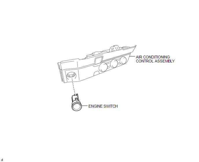
Components
COMPONENTS
ILLUSTRATION
Inspection
INSPECTION
PROCEDURE
1. INSPECT ENGINE SWITCH
(a) Measure the resistance according to the value(s) in the table below.
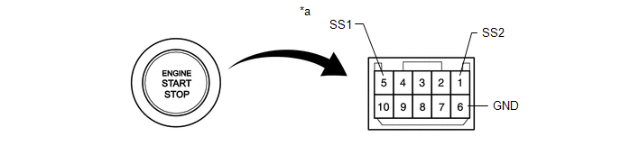 Text in Illustration
|
*a |
Component without harness connected (Engine Switch) |
- |
- |
Standard Resistance:
|
Tester Connection |
Switch Condition |
Specified Condition |
|---|---|---|
|
5 (SS1) - 6 (GND) |
Not pushed |
10 kΩ or higher |
|
1 (SS2) - 6 (GND) |
||
|
5 (SS1) - 6 (GND) |
Pushed |
Below 1 Ω |
|
1 (SS2) - 6 (GND) |
If the result is not as specified, replace the engine switch.
(b) Apply battery voltage between the terminals of the switch, and check the illumination condition of the engine switch.
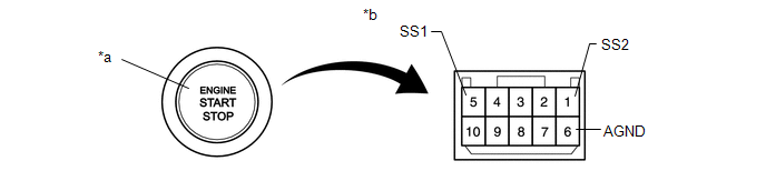 Text in Illustration
|
*a |
Indicator Light |
*b |
Component without harness connected (Engine Switch) |
OK:
|
Measurement Condition |
Specified Condition |
|---|---|
|
Battery positive (+) → Terminal 9 (SWIL) Battery negative (-) → Terminal 6 (GND) |
Illuminates |
HINT:
- If a positive (+) battery lead and a negative (-) battery lead are incorrectly connected, the engine switch indicator light will not illuminate.
- If the voltage is too low, the indicator light will not illuminate.
If the result is not as specified, replace the engine switch.
Installation
INSTALLATION
PROCEDURE
1. INSTALL ENGINE SWITCH
(a) Engage the 2 claws and install the engine switch to the air conditioning control assembly.
2. REMOVE AIR CONDITIONING CONTROL ASSEMBLY
(See page .gif) )
)
Removal
REMOVAL
PROCEDURE
1. REMOVE AIR CONDITIONING CONTROL ASSEMBLY
Seepage .gif)
2. REMOVE ENGINE SWITCH
|
(a) Disengage the 2 claws and remove the engine switch from the air conditioning control assembly. |
|
 2gr-fks Starting
...
 Ignition Switch
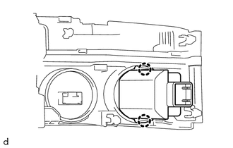
Components
COMPONENTS
ILLUSTRATION
Removal
REMOVAL
PROCEDURE
1. REMOVE LOWER STEERING COLUMN COVER
(a) Remove the 2 screws.
(b) Disengage the 2 claws and remove the lower steering colu ...
Other materials:
Electronic Circuit Inspection Procedure
ELECTRONIC CIRCUIT INSPECTION PROCEDURE
1. BASIC INSPECTION
(a) WHEN MEASURING RESISTANCE OF ELECTRONIC PARTS
(1) Unless otherwise stated, all resistance measurements should be made at an
ambient temperature of 20°C (68°F). Resistance measurements may be inaccurate if
measured at high tempe ...
High Pitched Horn
Components
COMPONENTS
ILLUSTRATION
Removal
REMOVAL
PROCEDURE
1. REMOVE RADIATOR GRILLE
Click here
2. REMOVE HIGH PITCHED HORN ASSEMBLY
(a) Disconnect the connector.
(b) Remove the bolt and high pitched horn assembly.
Inspection
...
Operation Check
OPERATION CHECK
1. MALFUNCTION DISPLAY (MULTI-INFORMATION DISPLAY)
(a) Open circuit indication
(1) If there is an open circuit between a No. 1 ultrasonic sensor and the clearance
warning ECU assembly or a sensor is malfunctioning, the malfunction is displayed
as shown in the illustration.
...
