Toyota Tacoma (2015-2018) Service Manual: Open or Short in Front Speed Sensor RH Circuit (C1405,C1406)
DESCRIPTION
Refer to DTCs C1401 and C1402 (See page .gif) ).
).
|
DTC Code |
DTC Detection Condition |
Trouble Area |
|---|---|---|
|
C1405 C1406 |
Either condition is met:
|
|
HINT:
- DTC C1405 is for the front speed sensor RH.
- DTC C1406 is for the front speed sensor LH.
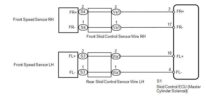
WIRING DIAGRAM
CAUTION / NOTICE / HINT
NOTICE:
- When replacing the skid control ECU (master cylinder solenoid), perform
calibration (See page
).
- Check the speed sensor signal after replacement (See page
).
PROCEDURE
|
1. |
CHECK HARNESS AND CONNECTOR (MOMENTARY INTERRUPTION) |
(a) Using the Techstream, check for any momentary interruption in the wire harness
and connector corresponding to the DTC (See page
).
|
Tester Display |
Measurement Item/Range |
Normal Condition |
Diagnostic Note |
|---|---|---|---|
|
FR Speed Open |
Front speed sensor RH open detection/ Error or Normal |
Normal |
- |
|
FL Speed Open |
Front speed sensor LH open detection/ Error or Normal |
Normal |
- |
OK:
Normal (there are no momentary interruptions).
HINT:
Perform the above inspection before removing the sensor and connector.
| NG | .gif) |
GO TO STEP 4 |
|
.gif)
|
2. |
READ VALUE USING TECHSTREAM (FRONT SPEED SENSOR) |
| NG | |
GO TO STEP 4 |
|
|
3. |
RECONFIRM DTC |
(a) Clear the DTCs (See page
).
(b) Turn the ignition switch off.
(c) Start the engine.
(d) Drive the vehicle at a speed of 40 km/h (25 mph) or more for at least 60 seconds.
(e) Check if the same DTC is output (See page
).
|
Result |
Proceed to |
|---|---|
|
DTCs C1405 and C1406 are not output |
A |
|
DTCs C1405 and/or C1406 are output |
B |
| A | |
USE SIMULATION METHOD TO CHECK |
| B | |
REPLACE MASTER CYLINDER SOLENOID |
|
4. |
INSPECT SKID CONTROL SENSOR WIRE |
(a) Remove the skid control sensor wire.
|
(b) Measure the resistance according to the value(s) in the table below. Standard Resistance: RH
|
|
| NG | |
REPLACE SKID CONTROL SENSOR WIRE |
|
|
5. |
CHECK HARNESS AND CONNECTOR (SKID CONTROL ECU - FRONT SPEED SENSOR) |
(a) Install the skid control sensor wire.
(b) Disconnect the S1 skid control ECU (master cylinder solenoid) connector.
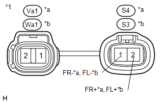
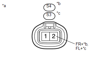
(c) Disconnect the S4 and/or S3 front speed sensor connector.
(d) Measure the resistance according to the value(s) in the table below.
Standard Resistance:
RH|
Tester Connection |
Condition |
Specified Condition |
|---|---|---|
|
S1-3 (FR+) - S4-2 (FR+) |
Always |
Below 1 Ω |
|
S1-3 (FR+) - Body ground |
Always |
10 kΩ or higher |
|
S1-17 (FR-) - S4-1 (FR-) |
Always |
Below 1 Ω |
|
S1-17 (FR-) - Body ground |
Always |
10 kΩ or higher |
|
Tester Connection |
Condition |
Specified Condition |
|---|---|---|
|
S1-18 (FL+) - S3-2 (FL+) |
Always |
Below 1 Ω |
|
S1-18 (FL+) - Body ground |
Always |
10 kΩ or higher |
|
S1-4 (FL-) - S3-1 (FL-) |
Always |
Below 1 Ω |
|
S1-4 (FL-) - Body ground |
Always |
10 kΩ or higher |
| NG | |
REPAIR OR REPLACE HARNESS OR CONNECTOR |
|
|
6. |
INSPECT SKID CONTROL ECU (FR+, FL+ TERMINAL) |
(a) Disconnect the S4 and/or S3 front speed sensor connector.
(b) Connect the S1 skid control ECU (master cylinder solenoid) connector.
|
(c) Measure the voltage according to the value(s) in the table below. Standard Voltage: RH
|
|
| OK | |
REPLACE FRONT SPEED SENSOR |
| NG | |
REPLACE MASTER CYLINDER SOLENOID |
 Acceleration Sensor Power Supply Voltage Malfunction (C1381)
DESCRIPTION
The skid control ECU (master cylinder solenoid) receives signals from the yaw
rate and acceleration (airbag sensor assembly) via the CAN communication system.
The airbag sensor assembl ...
 Open or Short in Rear Speed Sensor RH Circuit (C1407,C1408)
DESCRIPTION
Refer to DTCs C1401 and C1402 (See page ).
DTC Code
DTC Detection Condition
Trouble Area
C1407
C1408
Either condition is ...
Other materials:
System Description
SYSTEM DESCRIPTION
GENERAL
The cruise control main switch is used to turn the dynamic radar cruise control
system on and off, as well as operate 7 functions: SET, - (COAST), TAP-DOWN, RES
(RESUME), + (ACCEL), TAP-UP and CANCEL. The SET, TAP-DOWN, and - (COAST) functions,
and the RES (RESUME) ...
Air Inlet Control Servo Motor
Inspection
INSPECTION
PROCEDURE
1. INSPECT AIR INLET CONTROL SERVO MOTOR
(a) Inspect the servo motor operation.
(1) Connect the positive (+) lead from the battery to terminal 1 (FRS)
and negative (-) lead to terminals 2 (REC), then check that the shaft rotates
clockwise s ...
Horn System
Parts Location
PARTS LOCATION
ILLUSTRATION
Precaution
PRECAUTION
1. IGNITION SWITCH EXPRESSIONS
(a) The type of ignition switch used on this model differs depending on the specifications
of the vehicle. The expressions listed in the table below are used in this section.
Exp ...
