Toyota Tacoma (2015-2018) Service Manual: Horn System
Parts Location
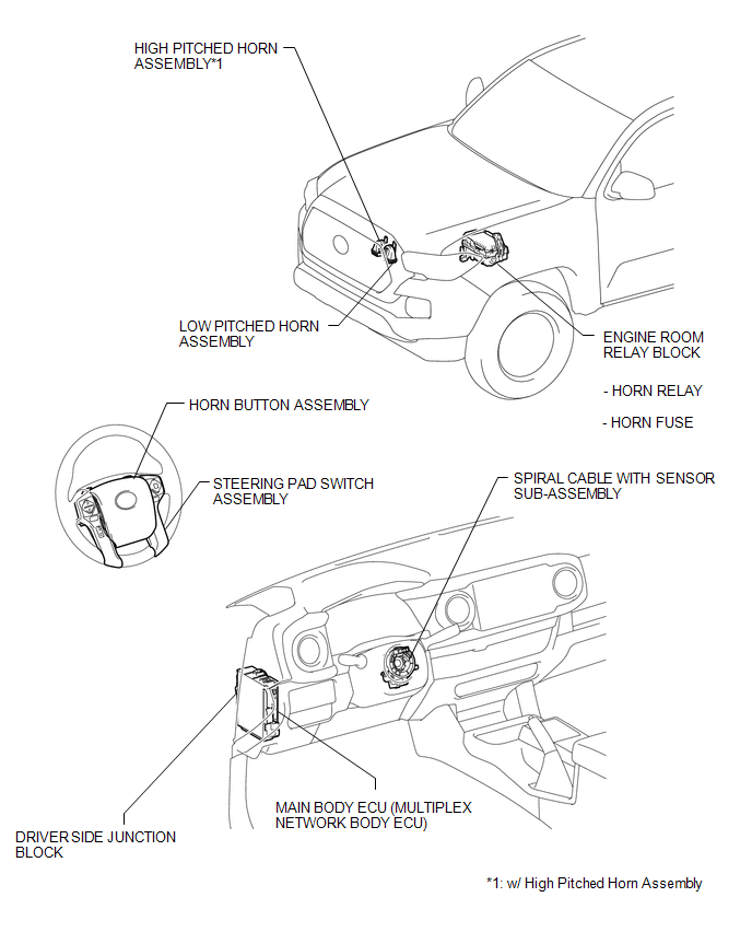
PARTS LOCATION
ILLUSTRATION
Precaution
PRECAUTION
1. IGNITION SWITCH EXPRESSIONS
(a) The type of ignition switch used on this model differs depending on the specifications of the vehicle. The expressions listed in the table below are used in this section.
|
Expression |
Ignition Switch (Position) |
Engine Switch (Condition) |
|---|---|---|
|
Ignition Switch off |
LOCK |
Off (Lock) |
|
Ignition Switch ACC |
ACC |
On (ACC) |
|
Ignition Switch ON |
ON |
On (IG) |
|
Engine Start |
START |
Start |
System Diagram
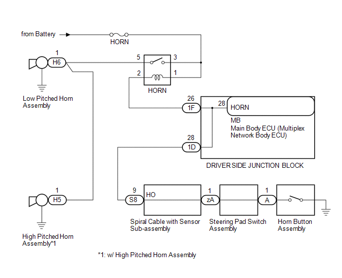
SYSTEM DIAGRAM
Data List / Active Test
DATA LIST / ACTIVE TEST
1. PERFORM ACTIVE TEST
HINT:
Using the Techstream to perform Active Tests allows relays, VSVs, actuators and other items to be operated without removing any parts. This non-intrusive functional inspection can be very useful because intermittent operation may be discovered before parts or wiring is disturbed. Performing Active Tests early in troubleshooting is one way to save diagnostic time. Data List information can be displayed while performing Active Tests.
(a) Connect the Techstream to the DLC3.
(b) Turn the ignition switch to ON.
(c) Turn the Techstream on.
(d) Enter the following menus: Body Electrical / Main Body / Active Test.
(e) Perform the Active Test according to the display on the Techstream.
Main Body|
Tester Display |
Test Part |
Control Range |
Diagnostic Note |
|---|---|---|---|
|
Vehicle Horn |
Vehicle horns |
ON/OFF |
- |
Problem Symptoms Table
PROBLEM SYMPTOMS TABLE
HINT:
Use the table below to help determine the cause of problem symptoms. If multiple suspected areas are listed, the potential causes of the symptoms are listed in order of probability in the "Suspected Area" column of the table. Check each symptom by checking the suspected areas in the order they are listed. Replace parts as necessary.
HORN SYSTEM|
Symptom |
Suspected Area |
See page |
|---|---|---|
|
Horn does not sound |
HORN fuse |
- |
|
HORN relay |
|
|
|
Horn button assembly |
- |
|
|
Steering pad switch assembly |
|
|
|
Spiral cable with sensor sub-assembly |
|
|
|
Driver side junction block |
- |
|
|
Harness or connector |
- |
|
|
Horn blows all the time |
HORN relay |
|
|
Horn button assembly |
- |
|
|
Steering pad switch assembly |
|
|
|
Spiral cable with sensor sub-assembly |
|
|
|
Driver side junction block |
- |
|
|
Main body ECU (Multiplex network body ECU) |
- |
|
|
Harness or connector |
- |
.gif)
 Horn Relay
On-vehicle Inspection
ON-VEHICLE INSPECTION
PROCEDURE
1. INSPECT HORN RELAY ASSEMBLY
(a) Check the resistance.
(1) Measure the resistance according to the value(s) in the table below ...
 Low Pitched Horn
Components
COMPONENTS
ILLUSTRATION
Inspection
INSPECTION
PROCEDURE
1. INSPECT LOW PITCHED HORN ASSEMBLY
(a) Check the operation.
(1) Apply battery voltage to the terminal 1 an ...
Other materials:
Installation
INSTALLATION
PROCEDURE
1. INSTALL EXHAUST MANIFOLD SUB-ASSEMBLY LH
(a) Install a new gasket to the cylinder head LH.
NOTICE:
Be careful of the installation direction.
(b) Temporarily install the exhaust manifold sub-assembly LH with the 4 nuts.
(c) Tighten the 4 nuts in the sequenc ...
Installation
INSTALLATION
CAUTION / NOTICE / HINT
HINT:
The following procedures are for BD22 (w/ Differential Lock).
PROCEDURE
1. INSTALL REAR DIFFERENTIAL CARRIER ASSEMBLY
(a) Clean the contact surfaces of the rear differential carrier assembly and
axle housing.
(b) Install the rear differential carri ...
Engine Control System Malfunction (C1201)
DESCRIPTION
If a malfunction in the engine control system is detected, VSC and TRAC operations
are prohibited by the fail-safe function.
DTC No.
Detection Item
DTC Detection Condition
Trouble Area
C1201
Engine Control System ...
