Toyota Tacoma (2015-2018) Service Manual: Open in Occupant Classification ECU Battery Positive Line (B1794)
DESCRIPTION
DTC B1794 is set when a malfunction is detected in the occupant detection ECU.
|
DTC No. |
DTC Detections Conditions |
Trouble Areas |
|---|---|---|
|
B1794 |
|
|
HINT:
- When DTC B1650/32 is detected as a result of troubleshooting the supplemental restraint system, perform troubleshooting for DTC B1794 of the occupant classification system.
- Use the Techstream to check for DTCs of the occupant detection ECU, otherwise the DTCs cannot be read.
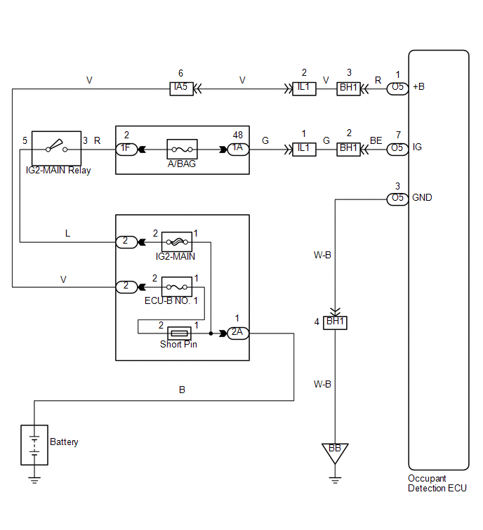
WIRING DIAGRAM
PROCEDURE
|
1. |
CHECK DTC |
(a) Turn the ignition switch to ON.
(b) Clear any DTCs stored in the memory (See page
.gif) ).
).
HINT:
- First clear DTCs stored in the occupant detection ECU and then in the airbag sensor assembly.
- Use the Techstream to clear the DTCs of the occupant detection ECU, otherwise the DTCs cannot be cleared.
(c) Turn the ignition switch off, and wait for at least 10 seconds.
(d) Turn the ignition switch to ON.
(e) Using the Techstream, check for DTCs of the occupant detection ECU (See page
).
OK:
DTC B1794 is not output.
HINT:
DTCs other than B1794 may be output at this time, but they are not related to this check.
| OK | .gif) |
USE SIMULATION METHOD TO CHECK |
|
.gif)
|
2. |
CHECK CONNECTION OF CONNECTORS |
(a) Turn the ignition switch off.
(b) Disconnect the negative (-) terminal cable from the battery, and wait for at least 90 seconds.
(c) Check that the connectors are properly connected to the airbag sensor assembly and the occupant detection ECU.
OK:
The connectors are properly connected.
| NG | |
CONNECT CONNECTORS |
|
|
3. |
CHECK CONNECTORS |
(a) Check that the connectors (on the occupant detection ECU side) are not damaged
(See page ).
OK:
The connectors are not deformed or damaged.
| NG | |
REPAIR OR REPLACE WIRE HARNESS |
|
|
4. |
CHECK WIRE HARNESS (SOURCE VOLTAGE) |
|
(a) Turn the ignition switch off. |
|
(b) Disconnect the negative (-) terminal cable from the battery, and wait for at least 90 seconds.
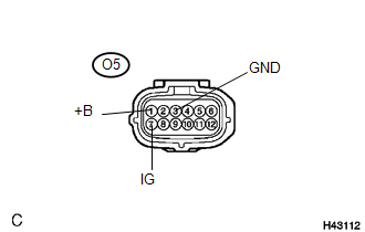
(c) Disconnect the O5 connector from the occupant detection ECU.
(d) Connect the negative (-) terminal cable to the battery.
(e) Turn the ignition switch to ON.
(f) Measure the voltage and resistance according to the value(s) in the table below.
Standard resistance:
|
Tester Connection |
Condition |
Specified Condition |
|---|---|---|
|
O5-3 (GND) - Body ground |
Always |
Below 1 Ω |
Standard voltage:
|
Tester Connection |
Switch Condition |
Specified Condition |
|---|---|---|
|
O5-1 (+B) - Body ground |
Ignition switch ON |
11 to 14 V |
|
O5-7 (IG) - Body ground |
Ignition switch ON |
11 to 14 V |
| NG | |
REPAIR OR REPLACE WIRE HARNESS OR BATTERY |
|
|
5. |
CHECK DTC |
(a) Turn the ignition switch off.
(b) Disconnect the negative (-) terminal cable from the battery, and wait for at least 90 seconds.
(c) Connect the connectors to the occupant detection ECU.
(d) Connect the negative (-) terminal cable to the battery, and wait for at least 2 seconds.
(e) Turn the ignition switch to ON.
(f) Clear any DTCs stored in the memory (See page
).
HINT:
- First clear DTCs stored in the occupant detection ECU and then in the airbag sensor assembly.
- Use the Techstream to clear the DTCs of the occupant detection ECU, otherwise the DTCs cannot be cleared.
(g) Turn the ignition switch off, and wait for at least 10 seconds.
(h) Turn the ignition switch to ON.
(i) Using the Techstream, check for DTCs of the occupant detection ECU (See page
).
OK:
DTC B1794 is not output.
HINT:
DTCs other than B1794 may be output at this time, but they are not related to this check.
| OK | |
USE SIMULATION METHOD TO CHECK |
|
|
6. |
REPLACE OCCUPANT DETECTION ECU |
(a) Turn the ignition switch off.
(b) Disconnect the negative (-) terminal cable from the battery, and wait for at least 90 seconds.
(c) Replace the occupant detection ECU (See page
).
HINT:
Perform the inspection using parts from a normal vehicle when possible.
|
|
7. |
PERFORM ZERO POINT CALIBRATION |
(a) Connect the negative (-) terminal cable to the battery.
(b) Connect the Techstream to the DLC3.
(c) Turn the ignition switch to ON.
(d) Using the Techstream, perform the zero point calibration (See page
).
OK:
"Zero Point Calibration is complete." is displayed on the Techstream.
|
|
8. |
PERFORM SENSITIVITY CHECK |
(a) Using the Techstream, perform the sensitivity check (See page
).
Standard :
27 to 33 kg (59.52 to 72.75 lb)
| NEXT | |
END |
 Diagnostic Trouble Code Chart
DIAGNOSTIC TROUBLE CODE CHART
If a trouble code is displayed during the DTC check, check the circuit listed
for the code in the table below (proceed to the page listed for that circuit).
1. Occupa ...
 Occupant Classification ECU Malfunction (B1795)
DESCRIPTION
DTC B1795 is set when a malfunction is detected in the occupant detection ECU.
Troubleshoot DTC B1771 first when both DTCs B1771 and B1795 are present.
DTC No.
DTC ...
Other materials:
Heater Circuit (C1AAE)
DESCRIPTION
The forward recognition camera controls the current supplied to the camera heater
(forward recognition hood).
If the forward recognition camera detects a malfunction in the camera heater
(forward recognition hood) circuit, DTC C1AAE is stored.
DTC No.
Detecti ...
Bottle holders
Front
Front console box (Separated type
front seat)
Rear (Double Cab models)
■Bottle holders
Depending on their size or shape, some bottles may not fit in the holders.
NOTICE
■Items that should not be stowed in the bottle holders
Put the cap on before stowing a bottle. Do ...
Fail-safe Chart
FAIL-SAFE CHART
HINT:
If any of the following auto cancel conditions are detected while the dynamic
radar cruise control system is controlling vehicle speed, the system clears the
stored vehicle speed and cancels control of vehicle speed by the dynamic radar cruise
control system.
Automatic ...
