Toyota Tacoma (2015-2018) Service Manual: Transfer Shift Motor Control Circuit Low (P17A9)
DESCRIPTION
This DTC is output when a short to ground in the transfer shift motor and A.D.D. shift motor drive circuit is detected.
|
DTC No. |
Detection Item |
DTC Detection Condition |
Trouble Area |
|---|---|---|---|
|
P17A9 |
Transfer Shift Motor Control Circuit Low |
|
|
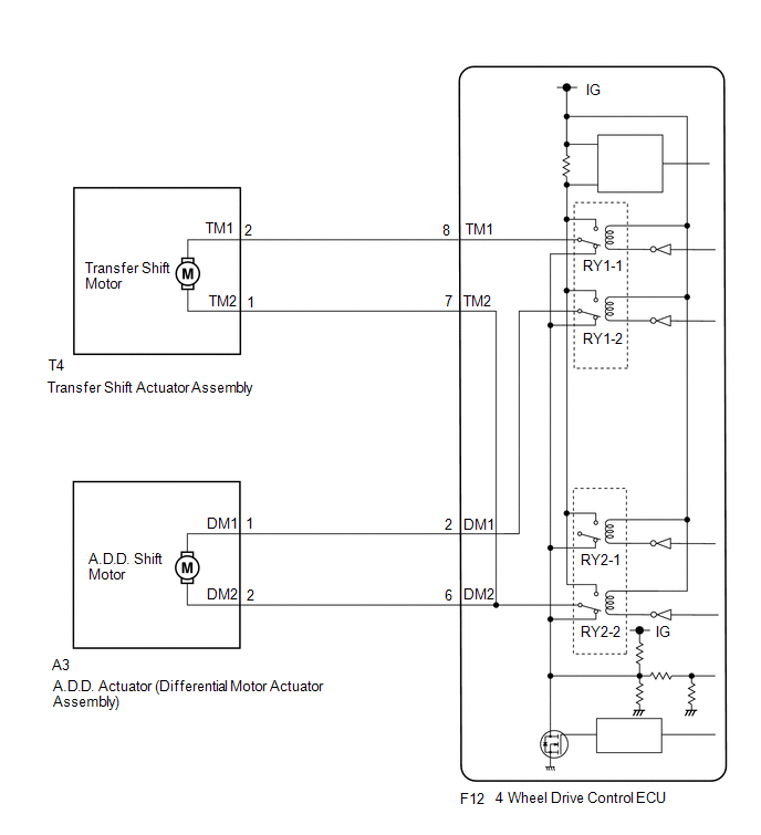
WIRING DIAGRAM
PROCEDURE
|
1. |
CHECK ACTUATOR ASSEMBLY (TRANSFER SHIFT MOTOR OR A.D.D. SHIFT MOTOR) |
(a) Disconnect the 4 wheel drive control ECU connector.
|
(b) Measure the resistance according to the value(s) in the table below. Standard Resistance: Transfer shift actuator assembly side:
|
|
|
Result |
Proceed to |
|---|---|
|
OK |
A |
|
NG (transfer shift actuator assembly side) |
B |
|
NG (A.D.D. actuator (differential vacuum actuator assembly) side) |
C |
| A | .gif) |
REPLACE 4 WHEEL DRIVE CONTROL ECU |
| C | |
GO TO STEP 3 |
|
.gif)
|
2. |
CHECK HARNESS AND CONNECTOR (4 WHEEL DRIVE CONTROL ECU AND TRANSFER SHIFT ACTUATOR ASSEMBLY - BODY GROUND) |
(a) Disconnect the F12 4 wheel drive control ECU connector.
(b) Disconnect the T4 transfer shift actuator assembly connector.
(c) Measure the resistance according to the value(s) in the table below.
Standard Resistance:
|
Tester Connection |
Condition |
Specified Condition |
|---|---|---|
|
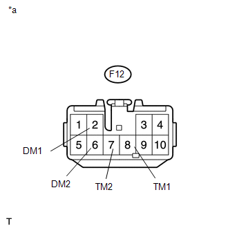
F12-8 (TM1) or T4-2 (TM1) - Body ground |
Always |
10 kΩ or higher |
|
F12-7 (TM2) or T4-1 (TM2) - Body ground |
Always |
10 kΩ or higher |
| OK | |
REPLACE TRANSFER SHIFT ACTUATOR ASSEMBLY |
| NG | |
REPAIR OR REPLACE HARNESS OR CONNECTOR |
|
3. |
CHECK HARNESS AND CONNECTOR (4 WHEEL DRIVE CONTROL ECU AND DIFFERENTIAL VACUUM ACTUATOR ASSEMBLY - BODY GROUND) |
(a) Disconnect the F12 4 wheel drive control ECU connector.
(b) Disconnect the A3 A.D.D. actuator (differential vacuum actuator assembly) connector.
(c) Measure the resistance according to the value(s) in the table below.
Standard Resistance:
|
Tester Connection |
Condition |
Specified Condition |
|---|---|---|
|
F12-2 (DM1) or A3-1 (DM1) - Body ground |
Always |
10 kΩ or higher |
|
F12-6 (DM2) or A3-2 (DM2) - Body ground |
Always |
10 kΩ or higher |
| OK | |
REPLACE DIFFERENTIAL VACUUM ACTUATOR ASSEMBLY |
| NG | |
REPAIR OR REPLACE HARNESS OR CONNECTOR |
 Four Wheel Drive (4WD) Range Signal Circuit Range / Performance (P279E)
DESCRIPTION
When the transfer position switch is switched, the 2-4 terminal and LO terminal
change to one of the following ON/OFF combinations listed in the table below.
Terminal
...
 Transfer Shift Motor Control Circuit High (P17AA)
DESCRIPTION
This DTC is output when a short to B+ in the transfer shift motor and A.D.D.
shift motor drive circuit is detected.
DTC No.
Detection Item
DTC Detectio ...
Other materials:
Installation
INSTALLATION
PROCEDURE
1. INSTALL TRANSFER POSITION SWITCH (for 4WD)
Click here
2. INSTALL ENGINE SWITCH
Click here
3. INSTALL AIR CONDITIONING CONTROL ASSEMBLY
(a) Connect the connectors.
(b) Engage the 8 clips to install the air conditioning control assembly.
4. INSTALL RADIO AND DISP ...
Installation
INSTALLATION
PROCEDURE
1. INSTALL STEERING COLUMN ASSEMBLY
(a) Install the steering column assembly with the 2 nuts and bolt.
Torque:
21 N·m {214 kgf·cm, 15 ft·lbf}
(b) Connect each of the connectors to the steering column assembly.
(c) Connect the wire harness clamps to the steering colu ...
Inspection
INSPECTION
PROCEDURE
1. INSPECT GENERATOR BRUSH HOLDER ASSEMBLY
(a) Using a vernier caliper, measure the brush length.
Text in Illustration
*a
Length
Standard exposed length:
9.5 to 11.5 mm (0.374 to 0.453 in.)
Minimum ex ...
