Toyota Tacoma (2015-2018) Service Manual: On-vehicle Inspection
ON-VEHICLE INSPECTION
PROCEDURE
1. CHECK FUEL PUMP ASSEMBLY OPERATION
(a) Check fuel pressure.
(1) Connect the Techstream to the DLC3.
(2) Start the engine.
(3) Turn the Techstream on.
(4) Enter the following menus: Powertrain / Engine / Active Test / Control the Target Fuel Pressure.
(5) Check that the fuel pressure fluctuates when the target fuel pressure changes.
HINT:
The target fuel pressure operation lowers the target fuel pressure by 12.5% or increases the target fuel pressure by 25%.
Standard:
Fuel pressure fluctuates in accordance with the Techstream operation.
If the result is not as specified, replace the fuel delivery pipe sub-assembly (fuel pressure sensor).
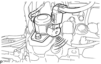
(b) Check operating sound.
(1) Remove the V-bank cover sub-assembly (See page
.gif) ).
).
(2) Start the engine.
|
(3) Using a sound scope, check the operating sound of the pump. If no sound can be heard, check the fuel pump, wire harness and ECM. |
|
(4) Stop the engine.
(5) Install the V-bank cover sub-assembly (See page
).
 Components
COMPONENTS
ILLUSTRATION
*1
FUEL PUMP ASSEMBLY
*2
FUEL PUMP LIFTER ASSEMBLY
*3
FUEL PUMP LIFTER GUIDE
*4
...
 Removal
REMOVAL
PROCEDURE
1. REMOVE INTAKE MANIFOLD
(See page )
2. REMOVE WIRE HARNESS CLAMP BRACKET
(a) Remove the 2 bolts and wire harness clamp bracket.
...
Other materials:
Installation
INSTALLATION
PROCEDURE
1. INSTALL TRANSFER POSITION SWITCH (for 4WD)
Click here
2. INSTALL ENGINE SWITCH
Click here
3. INSTALL AIR CONDITIONING CONTROL ASSEMBLY
(a) Connect the connectors.
(b) Engage the 8 clips to install the air conditioning control assembly.
4. INSTALL RADIO AND DISP ...
Low Power Supply Voltage Malfunction (C1241)
DESCRIPTION
If a malfunction is detected in the power supply circuit, the skid control ECU
(brake actuator assembly) stores this DTC and the fail-safe function prohibits ABS
operation.
This DTC is stored when the +BS terminal voltage deviates from the DTC detection
condition due to a malfunc ...
Adjustment
ADJUSTMENT
CAUTION / NOTICE / HINT
NOTICE:
For vehicles equipped with VSC, if the wheel alignment has been adjusted, and
if suspension or underbody components have been removed/installed or replaced, be
sure to perform the following initialization procedure in order for the system to
functi ...
