Toyota Tacoma (2015-2018) Service Manual: Removal
REMOVAL
PROCEDURE
1. REMOVE INTAKE MANIFOLD
(See page .gif) )
)
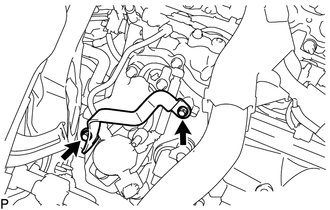
2. REMOVE WIRE HARNESS CLAMP BRACKET
|
(a) Remove the 2 bolts and wire harness clamp bracket. |
|
3. REMOVE FUEL TUBE SUB-ASSEMBLY
|
(a) Disconnect the fuel tube sub-assembly from the fuel pump assembly
(See page |
|
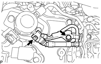
(b) Remove the bolt and fuel tube sub-assembly.
4. REMOVE NO. 1 FUEL PIPE SUB-ASSEMBLY
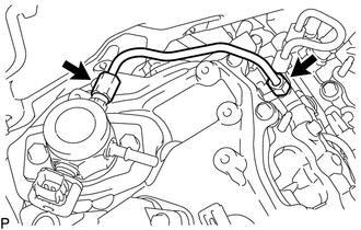
(a) Loosen the 2 union nuts of the No. 1 fuel pipe sub-assembly.
(b) Remove the No. 1 fuel pipe sub-assembly.
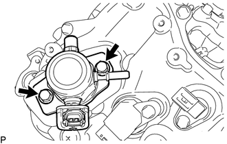
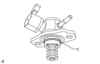
5. REMOVE FUEL PUMP ASSEMBLY
|
(a) Remove the 2 bolts and fuel pump assembly. |
|
|
(b) Remove the O-ring from the fuel pump assembly. |
|
(c) Remove the fuel pump lifter guide and fuel pump lifter assembly.
(d) Remove the fuel pump spacer gasket from the cylinder head cover sub-assembly.
 On-vehicle Inspection
ON-VEHICLE INSPECTION
PROCEDURE
1. CHECK FUEL PUMP ASSEMBLY OPERATION
(a) Check fuel pressure.
(1) Connect the Techstream to the DLC3.
(2) Start the engine.
(3) Turn the Techstream on.
(4) Ente ...
 Inspection
INSPECTION
PROCEDURE
1. INSPECT FUEL PUMP ASSEMBLY
(a) Measure the resistance according to the value(s) in the table below.
Standard Resistance:
Tester Connection
Condition ...
Other materials:
System Description
SYSTEM DESCRIPTION
1. SRS (SUPPLEMENTAL RESTRAINT SYSTEM) AIRBAG SYSTEM
(a) General Description
(1) The SRS airbag system consists of the following airbag and main components:
Airbag
Access Cab Model
Double Cab Model
Driver Airbag
Stan ...
Terminals Of Ecu
TERMINALS OF ECU
1. CHECK AIR CONDITIONING AMPLIFIER ASSEMBLY
(a) Disconnect the A36 air conditioning amplifier assembly connector.
(b) Measure the voltage and resistance according to the value(s) in the table
below.
HINT:
Measure the values on the wire harness side with the connector disco ...
Vehicle Speed Sensor Circuit (C1AA3)
DESCRIPTION
The forward recognition camera receives vehicle speed signals from the skid control
ECU. If the skid control ECU receives a vehicle speed sensor malfunction signal,
it informs the forward recognition camera via CAN communication, and DTC C1AA3 is
stored.
DTC No.
...
