Toyota Tacoma (2015-2018) Service Manual: Components
COMPONENTS
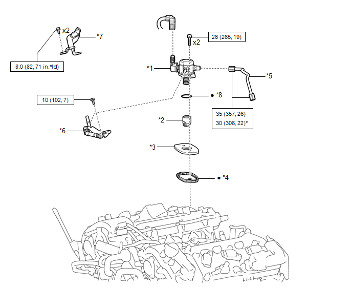
ILLUSTRATION
|
*1 |
FUEL PUMP ASSEMBLY |
*2 |
FUEL PUMP LIFTER ASSEMBLY |
|
*3 |
FUEL PUMP LIFTER GUIDE |
*4 |
FUEL PUMP SPACER GASKET |
|
*5 |
NO. 1 FUEL PIPE SUB-ASSEMBLY |
*6 |
FUEL TUBE SUB-ASSEMBLY |
|
*7 |
WIRE HARNESS CLAMP BRACKET |
*8 |
O-RING |
.png) |
N*m (kgf*cm, ft.*lbf): Specified torque |
* |
For use with union nut wrench |
|
â—Ź |
Non-reusable part |
- |
- |

 On-vehicle Inspection
ON-VEHICLE INSPECTION
PROCEDURE
1. CHECK FUEL PUMP ASSEMBLY OPERATION
(a) Check fuel pressure.
(1) Connect the Techstream to the DLC3.
(2) Start the engine.
(3) Turn the Techstream on.
(4) Ente ...
Other materials:
Installation
INSTALLATION
PROCEDURE
1. INSTALL STEERING PAD
(a) Check that the ignition switch is off.
(b) Check that the cable is disconnected from the negative (-) battery terminal.
CAUTION:
Wait at least 90 seconds after disconnecting the cable from the negative (-)
battery terminal to disable the SRS ...
Removal
REMOVAL
CAUTION / NOTICE / HINT
HINT:
When removing the name plates or stripe tapes, heat the vehicle body or tail
gate and name plates or stripe tapes using a heat light.
Heating Temperature
Item
Temperature
Vehicle Body or Tail Gate
40 to 60 ...
Air Inlet Damper Control Servo Motor Circuit (B1442/42)
DESCRIPTION
This No. 1 air conditioning servo assembly (fresh/recirculation damper) is controlled
by the air conditioning amplifier assembly and moves the air inlet damper to the
desired position.
DTC No.
DTC Detection Condition
Trouble Area
B1 ...
