Toyota Tacoma (2015-2018) Service Manual: Fuel Pressure Sensor
Components
COMPONENTS
ILLUSTRATION
Inspection
INSPECTION
PROCEDURE
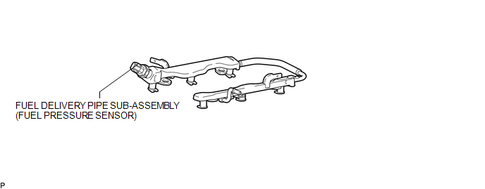
1. INSPECT FUEL DELIVERY PIPE SUB-ASSEMBLY (FUEL PRESSURE SENSOR)
NOTICE:
- Do not remove the fuel pressure sensor from the fuel delivery pipe sub-assembly.
- If a fuel pressure sensor is removed, replace the fuel delivery pipe sub-assembly with a new one.
(a) Remove the fuel delivery pipe sub-assembly (See page
.gif) ).
).
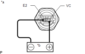
(b) Check the fuel pressure sensor output voltage.
|
(1) Apply 5 V between terminals 1 (VC) and 3 (E2). Text in Illustration
NOTICE:
HINT: If a stable power supply is not available, use 4 1.2 V nickel-metal hydride batteries or equivalent. |
|
|
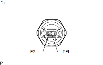
(2) Measure the voltage between terminals. Text in Illustration
Standard Voltage:
If the result is not as specified, replace the fuel delivery pipe sub-assembly. |
|
(c) Install the fuel delivery pipe sub-assembly (See page
).
Installation
INSTALLATION
CAUTION / NOTICE / HINT
HINT:
Perform "Inspection After Repairs" after replacing the fuel delivery pipe sub-assembly
(fuel pressure sensor) (See page .gif) ).
).
PROCEDURE
1. INSTALL FUEL DELIVERY PIPE SUB-ASSEMBLY (FUEL PRESSURE SENSOR)
(See page )
NOTICE:
- Do not remove the fuel pressure sensor from the fuel delivery pipe sub-assembly.
- If a fuel pressure sensor is removed, replace the fuel delivery pipe sub-assembly (fuel pressure sensor) with a new one.
HINT:
Perform "Inspection After Repairs" after replacing the fuel delivery pipe sub-assembly
(fuel pressure sensor) (See page ).
Removal
REMOVAL
PROCEDURE
1. REMOVE FUEL DELIVERY PIPE SUB-ASSEMBLY (FUEL PRESSURE SENSOR)
(See page .gif) )
)
NOTICE:
- Do not remove the fuel pressure sensor from the fuel delivery pipe sub-assembly.
- If a fuel pressure sensor is removed, replace the fuel delivery pipe sub-assembly (fuel pressure sensor) with a new one.
 Fuel Main Valve
Components
COMPONENTS
ILLUSTRATION
Removal
REMOVAL
PROCEDURE
1. REMOVE FUEL SUCTION TUBE WITH PUMP AND GAUGE ASSEMBLY
(See page )
2. REMOVE FUEL SENDER GAUGE ASSEMBLY
3. REMOVE NO. ...

Other materials:
Dtc Check / Clear
DTC CHECK / CLEAR
CHECK FOR DTC
(a) Connect the Techstream to the DLC3.
(b) Turn the ignition switch to ON.
(c) Turn the Techstream on.
(d) Enter the following menus: Body Electrical / Central Gateway / Trouble Codes.
(e) Read the DTCs.
CLEAR DTC
(a) Connect the Techstream to the DLC3.
(b) ...
Installation
INSTALLATION
PROCEDURE
1. INSTALL REAR BUMPER ASSEMBLY
(a) Using an engine lifter or equivalent, engage the 2 pins to install the rear
bumper assembly as shown in the illustration.
Text in Illustration
*a
Pin
-
-
NOTICE:
Using pl ...
Front Occupant Classification Sensor LH Collision Detection (B1785)
DESCRIPTION
DTC B1785 is set when the occupant detection ECU receives a collision detection
signal, which is sent by the occupant classification sensor front LH when an accident
occurs.
DTC B1785 is also set when the front seat with adjuster frame assembly RH is
subjected to a strong impact, ...
