Toyota Tacoma (2015-2018) Service Manual: Installation
INSTALLATION
PROCEDURE
1. INSTALL MAIN BODY ECU (MULTIPLEX NETWORK BODY ECU)
NOTICE:
- Make sure that the connecting surfaces are free of foreign matter.
- Do not touch the main body ECU (multiplex network body ECU) connector.
|
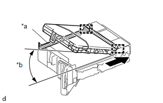
(a) Set the main body ECU (multiplex network body ECU) to the position where the 2 guides of the main body ECU (multiplex network body ECU) contacts the housing sidewall of the driver side junction block as shown in the illustration. Text in Illustration
HINT: Make sure to keep the angle at 20┬░ or more as shown in the illustration. |
|
|
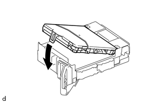
(b) While keeping the main body ECU (multiplex network body ECU) in contact with driver side junction block (axis of rotation), lower it as shown in the illustration. |
|
|
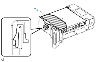
(c) Press the push area until the claw engages to install the main body ECU (multiplex network body ECU). Text in Illustration
NOTICE:
HINT: If a click sound cannot be heard, visually check the engagement of the lock. The engagement can also be confirmed if the main body ECU (multiplex network body ECU) and driver side junction block are flush. |
|
2. INSTALL DRIVER SIDE JUNCTION BLOCK
(a) Connect the 2 connectors on the back side.
(b) Install the driver side junction block with the 2 nuts.
(c) Connect the 5 connectors on the front side.
3. INSTALL INSTRUMENT PANEL LOWER FINISH PANEL SUB-ASSEMBLY
(See page .gif) )
)
 Components
COMPONENTS
ILLUSTRATION
ILLUSTRATION
...
 Removal
REMOVAL
PROCEDURE
1. REMOVE INSTRUMENT PANEL LOWER FINISH PANEL SUB-ASSEMBLY
(See page )
2. REMOVE DRIVER SIDE JUNCTION BLOCK
(a) Disconnect the 5 connectors on the front side.
...
Other materials:
Removal
REMOVAL
PROCEDURE
1. REMOVE REAR WHEEL
2. DRAIN BRAKE FLUID
HINT:
Immediately wash off any brake fluid that comes into contact with any painted
surfaces.
3. REMOVE REAR BRAKE DRUM SUB-ASSEMBLY
(a) Release the parking brake, and remove the rear brake drum.
If the rear brake drum cannot be ...
Calibration
CALIBRATION
1. DESCRIPTION
(a) After replacing the VSC relevant components or performing "Front wheel alignment
adjustment", clearing and reading the sensor calibration data are necessary.
(b) Follow the chart to perform calibration.
Replacing Parts
Necessary Op ...
Propeller Shaft System
Problem Symptoms Table
PROBLEM SYMPTOMS TABLE
HINT:
Use the table below to help determine the cause of problem symptoms. If multiple
suspected areas are listed, the potential causes of the symptoms are listed in order
of probability in the "Suspected Area" column of the table. Che ...
