Toyota Tacoma (2015-2018) Service Manual: Lost Communication with Alternator Missing Message (P161A87)
DESCRIPTION
The ECM communicates with the generator assembly via LIN communication. If a LIN communication error is detected, the ECM stores this DTC.
|
DTC No. |
DTC Detection Condition |
Trouble Area |
|---|---|---|
|
P161A87 |
Generator assembly or ECM communication stop for about 17 minutes or more with the ignition switch ON. (1 trip detection logic) |
|
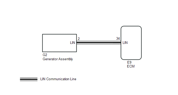
WIRING DIAGRAM
PROCEDURE
|
1. |
CHECK CHARGING SYSTEM |
(a) Check the charging system (See page .gif) ).
).
| NG | .gif) |
REPAIR OR REPLACE CHARGING SYSTEM |
|
.gif)
|
2. |
CHECK HARNESS AND CONNECTOR (ECM - GENERATOR ASSEMBLY) |
(a) Disconnect the E9 ECM connector.
(b) Disconnect the G2 generator assembly connector.
(c) Measure the resistance according to the value(s) in the table below.
Standard Resistance:
|
Tester Connection |
Condition |
Specified Condition |
|---|---|---|
|
E9-34 (LIN) - G2-2 (LIN) |
Always |
Below 1 Ω |
|
E9-34 (LIN) or G2-2 (LIN) - Body ground |
Always |
10 kΩ or higher |
| OK | |
REPLACE GENERATOR ASSEMBLY |
| NG | |
REPAIR OR REPLACE HARNESS OR CONNECTOR |
 On-vehicle Inspection
ON-VEHICLE INSPECTION
PROCEDURE
1. CHECK BATTERY CONDITION
NOTICE:
If the battery is weak or if the engine is difficult to start, recharge the battery
and perform inspections again before return ...
 Charging Failure
PROCEDURE
1.
CHECK GENERATOR PULLEY WITH CLUTCH (ON-VEHICLE INSPECTION)
(a) Start the engine and visually check if the fan of the generator rotor assembly
located i ...
Other materials:
Installation
INSTALLATION
CAUTION / NOTICE / HINT
CAUTION:
Some of these service operations affect the SRS airbag system. Read
the precautionary notices concerning the SRS airbag system before servicing
(See page ).
If the side airbag was deployed, replace the front seat assembly with
...
What to do if...
■ Instrument cluster
■ Center panel
■Warning lights
*1: Slip indicator comes on.
*2: The indicator flashes to indicate a malfunction.
GAS STATION INFORMATION
...
Lost Communication with ECM / PCM (U0100,U0140,U0142,U0155,U1117)
DESCRIPTION
These DTCs are stored when there is a CAN communication malfunction between the
certification ECU (smart key ECU assembly), ECM, main body ECU (multiplex network
body ECU) or combination meter assembly, and data from the option connector (bus
buffer ECU) cannot be received.
HINT: ...
