Toyota Tacoma (2015-2018) Service Manual: Radio Antenna
Components
COMPONENTS
ILLUSTRATION
Removal
REMOVAL
PROCEDURE
1. REMOVE ROOF HEADLINING ASSEMBLY (for Double Cab)
(See page .gif) )
)
2. REMOVE ROOF HEADLINING ASSEMBLY (for Access Cab)
(See page )
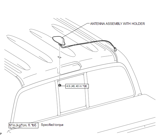
3. REMOVE ANTENNA ASSEMBLY WITH HOLDER
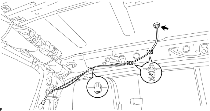
(a) Disengage the 3 clamps.
(b) Remove the nut.
|
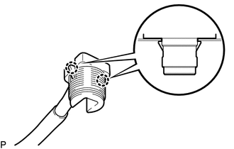
(c) Disengage the 2 claws to remove the antenna assembly with holder. |
|
Installation
INSTALLATION
PROCEDURE
1. INSTALL ANTENNA ASSEMBLY WITH HOLDER
(a) Engage the 2 claws to install the antenna assembly with holder.
(b) Install the nut.
Torque:
4.5 N·m {46 kgf·cm, 40 in·lbf}
(c) Engage the 3 clamps.
2. INSTALL ROOF HEADLINING ASSEMBLY (for Double Cab)
(See page .gif) )
)
3. INSTALL ROOF HEADLINING ASSEMBLY (for Access Cab)
(See page )
 Noise Filter(for 2tr-fe)
Components
COMPONENTS
ILLUSTRATION
Removal
REMOVAL
PROCEDURE
1. DISCONNECT CABLE FROM NEGATIVE BATTERY TERMINAL
2. REMOVE AIR CLEANER ASSEMBLY
(See page )
3. REMOVE RADIO SETTING COND ...
 Radio Antenna Cord
Components
COMPONENTS
ILLUSTRATION
Removal
REMOVAL
PROCEDURE
1. REMOVE INSTRUMENT PANEL SUB-ASSEMBLY
(See page )
2. REMOVE ANTENNA CORD SUB-ASSEMBLY
(a) Disengage the 4 clamps to remo ...
Other materials:
Air Mix Control Servo Motor
Inspection
INSPECTION
PROCEDURE
1. INSPECT AIR MIX CONTROL SERVO MOTOR (for Manual Air Conditioning System)
(a) Inspect the servo motor operation.
Text in Illustration
*a
0 V
*b
6V
...
Parts Location
PARTS LOCATION
ILLUSTRATION
*A
for Hydraulic Brake Booster
*B
for Vacuum Brake Booster
*C
w/ Toyota Safety Sense P
-
-
*1
BRAKE BOOSTER ASSEMBLY (SKID CONTROL ECU)
...
Removal
REMOVAL
PROCEDURE
1. REMOVE NO. 2 ENGINE UNDER COVER SUB-ASSEMBLY (w/ Off Road Package)
2. REMOVE NO. 1 ENGINE UNDER COVER SUB-ASSEMBLY
3. REMOVE FAN AND GENERATOR V BELT
4. DRAIN POWER STEERING FLUID
5. REMOVE FRONT FENDER APRON UPPER SEAL RH
6. DISCONNECT NO. 1 OIL RESERVOIR TO PUMP ...
