Toyota Tacoma (2015-2018) Service Manual: Neutral Position Switch Circuit
DESCRIPTION
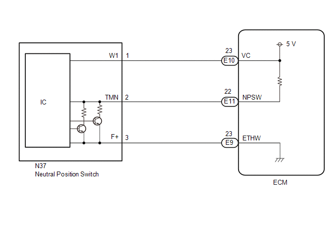
The ECM uses the neutral position switch installed to the manual transmission assembly to detect when the transmission is in the neutral position.
WIRING DIAGRAM
PROCEDURE
|
1. |
READ VALUE USING TECHSTREAM (NEUTRAL SWITCH) |
(a) Connect the Techstream to the DLC3.
(b) Turn the ignition switch to ON.
(c) Turn the Techstream on.
(d) Enter the following menus: Powertrain / Engine / Data List / Neutral Switch.
(e) Read the value when the shift lever is in neutral and any other position
OK:
|
Tester Display |
Condition |
Normal Condition |
|---|---|---|
|
Neutral Position Switch |
Shift lever is in neutral |
ON |
|
Shift lever is in any position other than neutral |
OFF |
| OK | .gif) |
USE SIMULATION METHOD TO CHECK |
|
.gif)
|
2. |
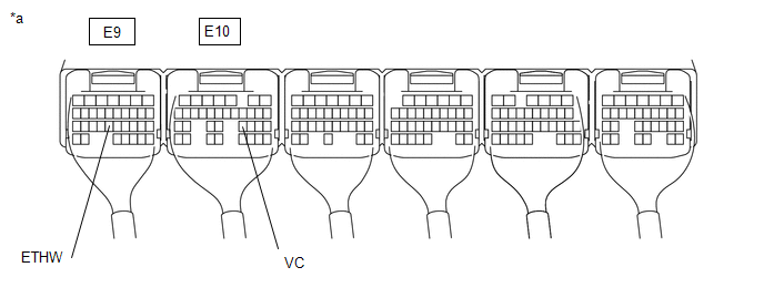
CHECK TERMINAL VOLTAGE (VC) |
(a) Turn the ignition switch to ON.
(b) Measure the voltage according to the value(s) in the table below.
|
*a |
Component with harness connected (ECM) |
- |
- |
Standard Voltage:
|
Tester Connection |
Condition |
Specified Condition |
|---|---|---|
|
E10-23 (VC) - E9-23 (ETHW) |
Ignition switch ON |
4.8 to 5.2 V |
| NG | |
GO TO SFI SYSTEM |
|
|
3. |
CHECK HARNESS AND CONNECTOR (ECM - NEUTRAL POSITION SWITCH) |
(a) Disconnect the E9, E10 and E11 ECM connectors.
(b) Disconnect the N37 neutral position switch connector.
(c) Measure the resistance according to the value(s) in the table below.
Standard Resistance:
|
Tester Connection |
Condition |
Specified Condition |
|---|---|---|
|
E10-23 (VC) - N37-1 (W1) |
Always |
Below 1 Ω |
|
E11-22 (NPSW) - N37-2 (TMN) |
Always |
Below 1 Ω |
|
E9-23 (ETHW) - N37-3 (F+) |
Always |
Below 1 Ω |
|
E10-23 (VC) or N37-1 (W1) - Body ground |
Always |
10 kΩ or higher |
|
E11-22 (NPSW) or N37-2 (TMN) - Body ground |
Always |
10 kΩ or higher |
|
E9-23 (ETHW) or N37-3 (F+) - Body ground |
Always |
10 kΩ or higher |
| NG | |
REPAIR OR REPLACE HARNESS OR CONNECTOR |
|
|
4. |
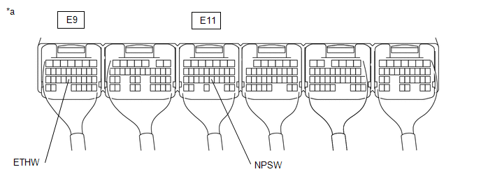
CHECK TERMINAL VOLTAGE (NPSW) |
(a) Measure the voltage according to the value(s) in the table below.
|
*a |
Component with harness connected (ECM) |
- |
- |
Standard Voltage:
|
Tester Connection |
Condition |
Specified Condition |
|---|---|---|
|
E11-22 (NPSW) - E9-23 (ETHW) |
Ignition switch ON, shift lever in neutral |
2.7 to 4.3 V |
|
Ignition switch ON, shift lever in any position other than neutral |
0.7 to 1.9 V |
| OK | |
REPLACE ECM |
|
|
5. |
REPLACE NEUTRAL POSITION SWITCH |
(a) Replace the neutral position switch.
Click here .gif)
|
|
6. |
READ VALUE USING TECHSTREAM (NEUTRAL SWITCH) |
(a) Connect the Techstream to the DLC3.
(b) Turn the ignition switch to ON.
(c) Turn the Techstream on.
(d) Enter the following menus: Powertrain / Engine / Data List / Neutral Switch.
(e) Read the value when the shift lever is in neutral and any other position
OK:
|
Tester Display |
Condition |
Normal Condition |
|---|---|---|
|
Neutral Switch |
Shift lever is in neutral |
ON |
|
Shift lever is in any position other than neutral |
OFF |
| OK | |
END |
| NG | |
REPLACE ECM |
 Cruise SET Indicator Light Circuit
DESCRIPTION
The ECM illuminates the cruise control SET indicator by sending indicator output
demand signals to the combination meter assembly via CAN communication. The cruise
control SET indicat ...

Other materials:
Diagnostic Trouble Code Chart
DIAGNOSTIC TROUBLE CODE CHART
Intuitive Parking Assist System
DTC Code
Detection Item
See page
C1AE6
Rear Left Sensor Malfunction
C1AE7
Rear Left Center Sensor Malfunction
...
Removal
REMOVAL
CAUTION / NOTICE / HINT
HINT:
If the bumper is damaged, there is a possibility that the installation area of
the blind spot monitor sensor may be deformed and the blind spot monitor system
may not operate correctly, so visually inspect the blind spot monitor sensor installation
area ...
Front Camera Module Circuit (C1AA0)
DESCRIPTION
When an internal malfunction is detected in the forward recognition camera, DTC
C1AA0 is stored.
DTC No.
Detection Item
DTC Detection Condition
Trouble Area
C1AA0
Front Camera Module Circuit
3 seconds ...
