Toyota Tacoma (2015-2018) Service Manual: Manual Shifting Test
MANUAL SHIFTING TEST
1. PERFORM MANUAL SHIFTING TEST
HINT:
- Using this test, it can be determined whether a problem is in an electrical circuit or if it is a mechanical problem in the transmission.
- If any abnormalities are found in the following test, the problem is in the transmission itself.
(a) Disconnect the connector of the transmission wire.
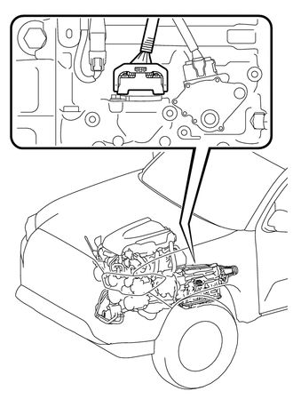
HINT:
It is possible to deactivate the electrical shift control by disconnecting the transmission wire. The gears can then be changed mechanically with the shift lever.
(b) Drive the vehicle with the transmission wire disconnected. Move the shift lever to each position to check whether the gear changes as shown in the table below.
|
Shift Lever Position |
Gear |
|---|---|
|
P |
P |
|
R |
R |
|
D |
3rd |
(c) Connect the connector of the transmission wire.
(d) Clear the DTCs (See page .gif) ).
).
 Initialization
INITIALIZATION
1. RESET MEMORY
NOTICE:
Perform Reset Memory (AT initialization) when replacing the automatic
transmission assembly, transmission valve body assembly or any of the shift ...
 Monitor Drive Pattern
MONITOR DRIVE PATTERN
1. TEST MONITOR DRIVE PATTERN FOR ECT
CAUTION:
Perform this drive pattern on a level surface and strictly observe the posted
speed limits and traffic laws while driving.
HI ...
Other materials:
Room Temperature Sensor Circuit (B1411/11)
DESCRIPTION
The cooler thermistor (room temperature sensor) is installed in the instrument
panel to detect the cabin temperature which is used to control the air conditioning
system AUTO mode. The resistance of the cooler thermistor (room temperature sensor)
changes in accordance with the cab ...
Clutch Switch Circuit
DESCRIPTION
While depressing the clutch pedal, the clutch start switch assembly sends a signal
to terminal MTN of the 4 wheel drive control ECU. While the signal is input, switching
between H4 and L4 is possible.
WIRING DIAGRAM
PROCEDURE
1.
READ VALUE USING TECHSTREA ...
Fail-safe Chart
FAIL-SAFE CHART
If there is a problem with sensor signals or actuator systems, the skid
control ECU prohibits power supply to the brake actuator assembly and informs
the ECM of a VSC system malfunction.
The brake actuator assembly turns off the solenoids and the ECM stops
its ...
