Toyota Tacoma (2015-2018) Service Manual: Monitor Drive Pattern
MONITOR DRIVE PATTERN
1. TEST MONITOR DRIVE PATTERN FOR ECT
CAUTION:
Perform this drive pattern on a level surface and strictly observe the posted speed limits and traffic laws while driving.
HINT:
Performing this drive pattern is one method to simulate the ECM (ECT) malfunction detection conditions.
Some DTCs may not be detected through ordinary, everyday driving. Also, DTCs may not be detected through this drive pattern.
(a) Preparation for driving
(1) Warm up the engine sufficiently (engine coolant temperature is 60°C (140°F) or higher).
(2) Drive the vehicle when the atmospheric temperature is -10°C (14°F) or higher.
Some malfunctions are not detected when the atmospheric temperature is below -10°C (14°F).
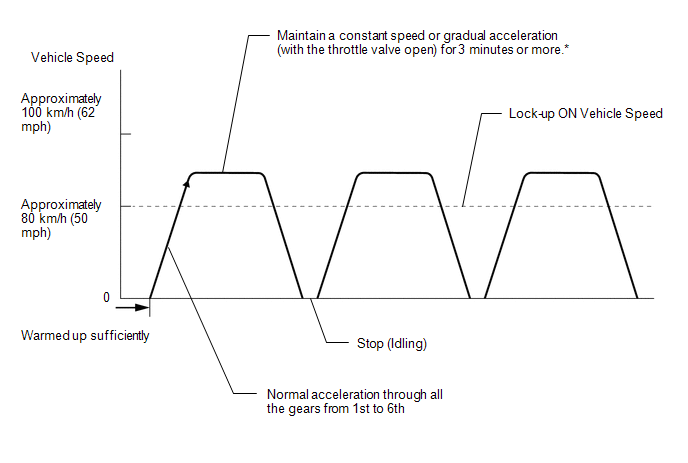
(b) Drive pattern
(1) Drive the vehicle through all the gears.
Stop → 1st → 2nd → 3rd → 4th → 5th → 6th → 6th (lock-up ON).
(2) Perform an engine brake test with the shift lever in S. While driving in the S6 range and 6th gear lock-up, move the shift lever to "-" and down-shift from 6th → 5th, 5th → 4th, 4th → 3rd, 3rd → 2nd and 2nd → 1st.
Check that engine braking is normal for every down-shift.
(3) Repeat the above drive pattern three times or more.
NOTICE:
- When using the Techstream, the monitor status can be checked in the
Data List (See page
.gif) ).
). - In the event that the drive pattern must be interrupted (due to traffic conditions or other factors), the drive pattern can be resumed and, in most cases, the monitor can be completed.
HINT:
*: Drive the vehicle at a speed in top gear that will cause lock-up to engage. The vehicle can be driven at a speed lower than that in the above diagram under the lock-up condition.
NOTICE:
It is necessary to drive the vehicle for approximately 30 minutes to detect DTC P071000 (No. 1 ATF temperature sensor malfunction).
 Manual Shifting Test
MANUAL SHIFTING TEST
1. PERFORM MANUAL SHIFTING TEST
HINT:
Using this test, it can be determined whether a problem is in an electrical
circuit or if it is a mechanical problem in the tr ...
 Problem Symptoms Table
PROBLEM SYMPTOMS TABLE
HINT:
Use the table below to help determine the cause of problem symptoms.
If multiple suspected areas are listed, the potential causes of the symptoms
are lis ...
Other materials:
Inspection
INSPECTION
PROCEDURE
1. INSPECT AUTO HIGH BEAM SWITCH
*a
Component without harness connected
(Auto High Beam Switch)
(a) Check the resistance.
(1) Measure the resistance according to the value(s) in the table below.
Standard Resistance:
Tester C ...
Extension Module Malfunction (B1552,B158A,B15BA)
DESCRIPTION
These DTCs are stored when a malfunction occurs in the extension module.
DTC Code
DTC Detection Condition
Trouble Area
B1552
Internal malfunction of the extension module
Stereo component tuner assembly
...
Radar Cruise Control Presence Determination Malfunction (Engine / HV) (C1A52)
DESCRIPTION
DTC C1A52 is stored when the ECM cannot recognize the millimeter wave radar sensor
assembly.
DTC No.
Detection Item
DTC Detection Condition
Trouble Area
MIL
C1A52
Radar Cruise Control Presence Determin ...
