Toyota Tacoma (2015-2018) Service Manual: LVDS Signal Malfunction (from Extension Module) (B1532,B156C)
DESCRIPTION
|
DTC Code |
DTC Detection Condition |
Trouble Area |
|---|---|---|
|
B1532 |
When one of the conditions below is met:
|
|
|
B156C |
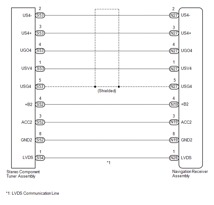
WIRING DIAGRAM
CAUTION / NOTICE / HINT
NOTICE:
After replacing the stereo component tuner assembly of vehicles subscribed to pay-type satellite radio broadcasts, XM radio ID registration is necessary. (w/ SDARS System)
PROCEDURE
|
1. |
CHECK DTC |
(a) Clear the DTCs (See page .gif) ).
).
(b) Check for DTCs (See page ).
OK:
No DTCs are output.
| OK | .gif) |
USE SIMULATION METHOD TO CHECK |
|
.gif)
|
2. |
CHECK HARNESS AND CONNECTOR (NAVIGATION RECEIVER ASSEMBLY - STEREO COMPONENT TUNER ASSEMBLY) |
(a) Disconnect the N19, N27 and N28 navigation receiver assembly connectors.
(b) Disconnect the S52, S53 and S54 stereo component tuner assembly connectors.
(c) Measure the resistance according to the value(s) in the table below.
Standard Resistance:
|
Tester Connection |
Condition |
Specified Condition |
|---|---|---|
|
N27-1 (USV4) - S53-1 (USV4) |
Always |
Below 1 Ω |
|
N27-2 (US4-) - S53-2 (US4-) |
Always |
Below 1 Ω |
|
N27-3 (US4+) - S53-3 (US4+) |
Always |
Below 1 Ω |
|
N27-4 (UGO4) - S53-4 (UGO4) |
Always |
Below 1 Ω |
|
N27-5 (USG4) - S53-5 (USG4) |
Always |
Below 1 Ω |
|
N19-4 (+B2) - S52-4 (+B) |
Always |
Below 1 Ω |
|
N19-3 (ACC2) - S52-3 (ACC2) |
Always |
Below 1 Ω |
|
N19-8 (GND2) - S52-8 (GND2) |
Always |
Below 1 Ω |
|
N28-1 (LVDS) - S54-1 (LVDS) |
Always |
Below 1 Ω |
|
N27-1 (USV4) - Body ground |
Always |
10 kΩ or higher |
|
N27-2 (US4-) - Body ground |
Always |
10 kΩ or higher |
|
N27-3 (US4+) - Body ground |
Always |
10 kΩ or higher |
|
N27-4 (UGO4) - Body ground |
Always |
10 kΩ or higher |
|
N27-5 (USG4) - Body ground |
Always |
10 kΩ or higher |
|
N19-4 (+B2) - Body ground |
Always |
10 kΩ or higher |
|
N19-3 (ACC2) - Body ground |
Always |
10 kΩ or higher |
|
N19-8 (GND2) - Body ground |
Always |
10 kΩ or higher |
|
N28-1 (LVDS) - Body ground |
Always |
10 kΩ or higher |
| NG | |
REPAIR OR REPLACE HARNESS OR CONNECTOR |
|
|
3. |
CHECK NO. 1 NAVIGATION WIRE |
(a) Replace the No. 1 navigation wire with a known good one (See page
).
(b) Clear the DTCs (See page ).
(c) Check for DTCs (See page ).
OK:
No DTCs are output.
| OK | |
END (NO. 1 NAVIGATION WIRE WAS DEFECTIVE) |
|
|
4. |
CHECK STEREO COMPONENT TUNER ASSEMBLY |
(a) Replace the stereo component tuner assembly with a known good one (See page
).
(b) Clear the DTCs (See page ).
(c) Check for DTCs (See page ).
OK:
No DTCs are output.
| OK | |
END (STEREO COMPONENT TUNER ASSEMBLY IS DEFECTIVE) |
| NG | |
REPLACE NAVIGATION RECEIVER ASSEMBLY |
 Lost Communication with Meter (B1324)
DESCRIPTION
This DTC is stored when a communication error occurs between the navigation receiver
assembly and combination meter assembly.
DTC No.
DTC Detection Condition
...
 HD Radio Tuner Malfunction (B1551,B15A0,B15AD,B15B0,B15B3,B15B4,B15B7)
DESCRIPTION
These DTCs are stored when a malfunction occurs in the navigation receiver assembly.
DTC No.
DTC Detection Condition
Trouble Area
B1551
...
Other materials:
Slip Indicator Light does not Come ON
DESCRIPTION
Refer to Slip Indicator Light Remains ON (See page
).
WIRING DIAGRAM
Refer to Slip Indicator Light Remains ON (See page
).
CAUTION / NOTICE / HINT
NOTICE:
When replacing the skid control ECU (brake actuator assembly), perform zero point
calibration and store system informatio ...
Dtc Check / Clear
DTC CHECK / CLEAR
1. CHECK FOR DTC
HINT:
When using the Techstream with the engine switch off, connect the Techstream
to the DLC3 and turn a courtesy light switch on and off at intervals of 1.5 seconds
or less until communication between the Techstream and the vehicle begins. Then
select th ...
Data List / Active Test
DATA LIST / ACTIVE TEST
1. DATA LIST
HINT:
Using the Techstream to read the Data List allows the values or states of switches,
sensors, actuators and other items to be read without removing any parts. This non-intrusive
inspection can be very useful because intermittent conditions or signals ...
