Toyota Tacoma (2015-2018) Service Manual: Lost Communication with HMI-LAN (B150A)
DESCRIPTION
The combination meter assembly receives a text data signal from the navigation receiver assembly or radio and display receiver assembly via local bus communication.
Based on this signal, navigation system information is displayed on the multi-information display.
This DTC is stored when the combination meter assembly cannot receive the signal.
|
DTC No. |
DTC Detection Condition |
Trouble Area |
|---|---|---|
|
B150A |
After the combination meter assembly receives a registration information signal, which is sent by the navigation receiver assembly when the ignition switch is ACC, 1 or more times, the combination meter assembly cannot receive the signal for 30 seconds or more. |
|
- *1: for Navigation Receiver Type
- *2: for Radio and Display Type
WIRING DIAGRAM
PROCEDURE
|
1. |
CHECK FOR DTC |
(a) Check if Navigation System or Audio and Visual System DTCs are output.
- for Navigation Receiver type: (See page
.gif) )
) - for Radio and Display type: (See page
)
OK:
Navigation system DTCs are not output.
Result|
Result |
Proceed to |
|---|---|
|
Navigation system DTCs are not output*1 |
A |
|
Navigation system DTCs are output*1 |
B |
|
Audio and visual system are not output*2 |
C |
|
Audio and Visual System are output*2 |
D |
- *1: for Navigation Receiver Type
- *2: for Radio and Display Type
| B | .gif) |
GO TO NAVIGATION SYSTEM |
| C | |
GO TO STEP 4 |
| D | |
GO TO AUDIO AND VISUAL SYSTEM |
|
.gif)
|
2. |
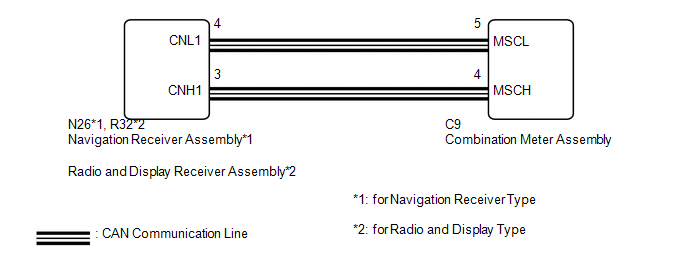
CHECK HARNESS AND CONNECTOR (COMBINATION METER ASSEMBLY - NAVIGATION RECEIVER ASSEMBLY) |
(a) Disconnect the C9 combination meter assembly connector.
(b) Disconnect the N26 navigation receiver assembly connector.
(c) Measure the resistance according to the value(s) in the table below.
Standard Resistance:
|
Tester Connection |
Condition |
Specified Condition |
|---|---|---|
|
C9-4 (MSCH) - N26-3 (CNH1) |
Always |
Below 1 Ω |
|
C9-5 (MSCL) - N26-4 (CNL1) |
Always |
Below 1 Ω |
|
C9-4 (MSCH) or N26-3 (CNH1) - Body ground |
Always |
10 kΩ or higher |
|
C9-5 (MSCL) or N26-4 (CNL1) - Body ground |
Always |
10 kΩ or higher |
| NG | |
REPAIR OR REPLACE HARNESS OR CONNECTOR |
|
|
3. |
REPLACE COMBINATION METER ASSEMBLY |
(a) Replace the combination meter assembly with a new or known good one (See
page ).
(b) Turn the ignition switch to ON and wait 30 seconds.
NOTICE:
A maximum of 30 seconds is required to send/receive the registration information between the combination meter assembly and navigation receiver assembly.
(c) Operate the steering pad switch assembly and check that the audio tab illuminates.
(d) Check for DTCs (See page ).
|
Result |
Proceed to |
|---|---|
|
The audio tab illuminates and DTC B150A is not output |
A |
|
The audio tab does not illuminate and DTC B150A is output |
B |
|
The audio tab does not illuminate and DTC B150A is output |
C |
| A | |
END (COMBINATION METER ASSEMBLY WAS DEFECTIVE) |
| B | |
REPLACE NAVIGATION RECEIVER ASSEMBLY |
| C | |
REPLACE RADIO AND DISPLAY RECEIVER ASSEMBLY |
|
4. |
CHECK HARNESS AND CONNECTOR (COMBINATION METER ASSEMBLY - RADIO AND DISPLAY RECEIVER ASSEMBLY) |
(a) Disconnect the C9 combination meter assembly connector.
(b) Disconnect the R32 radio and display receiver assembly connector.
(c) Measure the resistance according to the value(s) in the table below.
Standard Resistance:
|
Tester Connection |
Condition |
Specified Condition |
|---|---|---|
|
C9-4 (MSCH) - R32-3 (CNH1) |
Always |
Below 1 Ω |
|
C9-5 (MSCL) - R32-4 (CNL1) |
Always |
Below 1 Ω |
|
C9-4 (MSCH) or R32-3 (CNH1) - Body ground |
Always |
10 kΩ or higher |
|
C9-5 (MSCL) or R32-4 (CNL1) - Body ground |
Always |
10 kΩ or higher |
| NG | |
REPAIR OR REPLACE HARNESS OR CONNECTOR |
|
|
5. |
REPLACE COMBINATION METER ASSEMBLY |
(a) Replace the combination meter assembly with a new or known good one (See
page ).
(b) Turn the ignition switch to ON and wait 30 seconds.
NOTICE:
A maximum of 30 seconds is required to send/receive the registration information between the combination meter assembly and navigation receiver assembly.
(c) Operate the steering pad switch assembly and check that the audio tab illuminates.
(d) Check for DTCs (See page ).
|
Result |
Proceed to |
|---|---|
|
The audio tab illuminates and DTC B150A is not output |
A |
|
The audio tab does not illuminate and DTC B150A is output |
B |
| A | |
END (COMBINATION METER ASSEMBLY WAS DEFECTIVE) |
| B | |
REPLACE RADIO AND DISPLAY RECEIVER ASSEMBLY |
 Freeze Frame Data
FREEZE FRAME DATA
1. FREEZE FRAME DATA
(a) Whenever a meter DTC is detected, the combination meter assembly stores the
current vehicle state as freeze frame data.
2. CHECK FREEZE FRAME DATA
(a) ...
 Diagnostic Trouble Code Chart
DIAGNOSTIC TROUBLE CODE CHART
HINT:
If a trouble code is output during the DTC check, inspect the trouble areas listed
for that code. For details of the code, refer to the "See page".
...
Other materials:
Listening to a USB memory device
Connecting a USB memory device enables you to enjoy music from the vehicle
speakers.
Select “USB” on the “Select Audio Source” screen.
Connecting a USB memory device
Audio control screen
1. “Select Audio Source” screen appears
2. Displaying the folder list
3. Random playback
4 ...
How To Proceed With Troubleshooting
CAUTION / NOTICE / HINT
HINT:
Use the following procedure to troubleshoot the engine immobiliser system.
*: Use the Techstream.
PROCEDURE
1.
VEHICLE BROUGHT TO WORKSHOP
NEXT
2.
...
On-vehicle Inspection
ON-VEHICLE INSPECTION
PROCEDURE
1. INSPECT LOWER NO. 2 INSTRUMENT PANEL AIRBAG ASSEMBLY (for Vehicle not Involved
in Collision)
(a) Perform a diagnostic system check (See page
).
(b) With the lower No. 2 instrument panel airbag assembly ...
