Toyota Tacoma (2015-2018) Service Manual: Charging Failure
PROCEDURE
|
1. |
CHECK GENERATOR PULLEY WITH CLUTCH (ON-VEHICLE INSPECTION) |
(a) Start the engine and visually check if the fan of the generator rotor assembly located inside the generator assembly is operating.
OK:
The fan of the generator rotor assembly is operating.
| NG | .gif) |
REPLACE GENERATOR PULLEY WITH CLUTCH |
|
.gif)
|
2. |
CHECK GENERATOR PULLEY WITH CLUTCH (UNIT INSPECTION) |
(a) Remove the generator assembly (See page .gif) ).
).
(b) Check the installation condition of the generator pulley cap.
OK:
The generator pulley cap is not loose or missing.
(c) Check for grease leaks (for wet pulley) or particle formation due to friction (for dry pulley).
OK:
No grease leaks (for wet pulley) or large build-up of particles (for dry pulley).
(d) Check the generator with clutch pulley for misalignment (interference with the generator assembly).
OK:
The generator pulley with clutch is correctly aligned (no interference with the generator assembly).
|
(e) Turn the generator pulley with clutch clockwise and counterclockwise by hand and check for noise. OK: Noise does not occur when turned in both directions. |
|
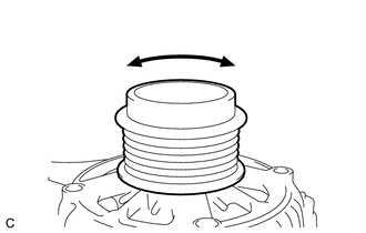
(f) Turn the generator pulley with clutch clockwise and counterclockwise by hand and visually check for runout.
OK:
The generator pulley with clutch does not have runout.
|
(g) Using a screwdriver, hold the fan of the generator rotor assembly located inside the generator assembly in place and check that the generator pulley with clutch locks when turned clockwise and turns freely when turned counterclockwise. |
|
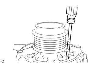
OK:
The generator pulley with clutch locks when turned clockwise and turns freely when turned counterclockwise.
| OK | |
REPAIR OR REPLACE GENERATOR ASSEMBLY |
| NG | |
REPLACE GENERATOR PULLEY WITH CLUTCH |
 Lost Communication with Alternator Missing Message (P161A87)
DESCRIPTION
The ECM communicates with the generator assembly via LIN communication. If a
LIN communication error is detected, the ECM stores this DTC.
DTC No.
DTC Detection C ...
 Noise Occurs from V-ribbed Belt or Generator Assembly
PROCEDURE
1.
CONFIRM PROBLEM SYMPTOM
(a) Confirm the problem symptom.
Result
Result
Proceed to
Noise occurs from fan and gene ...
Other materials:
Entune Audio
Operations such as listening to audio, using the hands-free phone, confirming
vehicle information and changing multimedia system settings are started by using
the following buttons.
Multimedia system operation buttons
button
Press this button to access the Bluetooth® hands-free system.
...
Installation
INSTALLATION
CAUTION / NOTICE / HINT
HINT:
Use the same procedure for both the RH and LH sides.
The procedure described below is for the LH side.
PROCEDURE
1. INSTALL FRONT SHOULDER BELT ANCHOR ADJUSTER ASSEMBLY
(a) As shown in the illustration, engage the 2 guides ...
Check Bus 3 Lines for Short Circuit
DESCRIPTION
There may be a short circuit between the CAN main bus lines and/or CAN branch
lines when the resistance between terminals 6 (CA3H) and 21 (CA3L) of the central
gateway ECU (network gateway ECU) is below 54 Ω.
Detection Item
Trouble Area
Resis ...
