Toyota Tacoma (2015-2018) Service Manual: Air Mix Damper Position Sensor Circuit (Driver Side) (B1436/36)
DESCRIPTION
This sensor detects the position of the air mix damper (for driver side) and sends the appropriate signals to the air conditioning amplifier assembly. The position sensor is built into the No. 3 air conditioning radiator damper servo sub-assembly (for driver side air mix).
|
DTC No. |
DTC Detection Condition |
Trouble Area |
|---|---|---|
|
B1436/36 |
Short to ground or power source circuit air mix damper position sensor (for driver side) circuit. |
|
WIRING DIAGRAM
PROCEDURE
|
1. |
READ VALUE USING TECHSTREAM |
(a) Connect the Techstream to the DLC3.
(b) Turn the ignition switch to ON.
(c) Turn the Techstream on.
(d) Operate the driver side temperature switch.
(e) Enter the following menus: Body Electrical / Air Conditioner / Data List.
(f) Check the value(s) by referring to the table below.
Air Conditioner|
Tester Display |
Measurement Item/Range |
Normal Condition |
Diagnostic Note |
|---|---|---|---|
|
Air Mix Damper Position (Driver Side) |
Air mix damper servo motor (for driver side) actual position / Min.: -14.0% Max.: 113.5% |
MAX COOL: 0.0% MAX HOT: 100.0% |
- |
|
Air Mix Damper Target (Driver Side) |
Air mix damper servo motor (for driver side) target position / Min.: -14.0% Max.: 113.5% |
MAX COOL: 0.0% MAX HOT: 100.0% |
- |
OK:
The display is as specified in the Normal Condition column.
|
Result |
Proceed to |
|---|---|
|
NG |
A |
|
OK (When troubleshooting according to Problem Symptoms Table) |
B |
|
OK (When troubleshooting according to the DTC) |
C |
| B | .gif) |
PROCEED TO NEXT SUSPECTED AREA SHOWN IN PROBLEM SYMPTOMS TABLE |
| C | |
REPLACE AIR CONDITIONING AMPLIFIER ASSEMBLY |
|
.gif)
|
2. |
INSPECT NO. 3 AIR CONDITIONING RADIATOR DAMPER SERVO SUB-ASSEMBLY (FOR DRIVER SIDE AIR MIX) |
(a) Remove the No. 3 air conditioning radiator damper servo sub-assembly (for
driver side air mix) (See page .gif) ).
).
(b) Inspect the No. 3 air conditioning radiator damper servo sub-assembly (for
driver side air mix) (See page ).
| NG | |
REPLACE NO. 3 AIR CONDITIONING RADIATOR DAMPER SERVO SUB-ASSEMBLY (FOR DRIVER SIDE AIR MIX) |
|
|
3. |
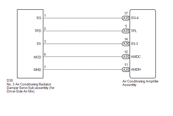
CHECK HARNESS AND CONNECTOR (NO. 3 AIR CONDITIONING RADIATOR DAMPER SERVO SUB-ASSEMBLY - AIR CONDITIONING AMPLIFIER ASSEMBLY) |
(a) Disconnect the D30 No. 3 air conditioning radiator damper servo sub-assembly (for driver side air mix) connector.
(b) Disconnect the A35 and A36 air conditioning amplifier assembly connectors.
(c) Measure the resistance according to the value(s) in the table below.
Standard Resistance:
|
Tester Connection |
Condition |
Specified Condition |
|---|---|---|
|
D30-1 (SG) - A35-17 (SG-4) |
Always |
Below 1 Ω |
|
D30-2 (TPD) - A35-5 (TPL) |
Always |
Below 1 Ω |
|
D30-3 (S5) - A36-14 (S5-3) |
Always |
Below 1 Ω |
|
D30-1 (SG) or A35-17 (SG-4) - Body ground |
Always |
10 kΩ or higher |
|
D30-2 (TPD) or A35-5 (TPL) - Body ground |
Always |
10 kΩ or higher |
|
D30-3 (S5) or A36-14 (S5-3) - Body ground |
Always |
10 kΩ or higher |
| OK | |
REPLACE AIR CONDITIONING AMPLIFIER ASSEMBLY |
| NG | |
REPAIR OR REPLACE HARNESS OR CONNECTOR |
 Air Outlet Damper Position Sensor Circuit (B1433/33)
DESCRIPTION
This sensor detects the position of the mode damper and sends the appropriate
signals to the air conditioning amplifier assembly. The position sensor is built
into the No. 1 air condi ...
 Air Inlet Damper Control Servo Motor Circuit (B1442/42)
DESCRIPTION
This No. 1 air conditioning servo assembly (fresh/recirculation damper) is controlled
by the air conditioning amplifier assembly and moves the air inlet damper to the
desired position ...
Other materials:
FCM Destination Information Uninitialized (C1AAA)
DESCRIPTION
When the forward recognition camera is replaced with a new one, the new forward
recognition camera attempts to store the country specification information received
from the main body ECU (multiplex network body ECU). If the forward recognition
camera cannot store the country speci ...
Portable Player cannot be Operated Using In-vehicle Device or Track Information
is not Displayed on In-vehicle Device
PROCEDURE
1.
CHECK USING ANOTHER "Bluetooth" AUDIO COMPATIBLE VEHICLE OF SAME MODEL
(a) Check if track information is displayed normally on another "Bluetooth" audio
compatible vehicle of the same model.
OK:
Track information is displayed no ...
Using a BluetoothÂź phone
The hands-free system is a function that allows you to use your cellular phone
without touching it.
This system supports BluetoothÂź. BluetoothÂź is a wireless data system that allows
the cellular phone to wirelessly connect to the hands-free system and make/receive
calls.
Before making a ph ...
