Toyota Tacoma (2015-2018) Service Manual: Key Reminder Buzzer does not Sound
DESCRIPTION
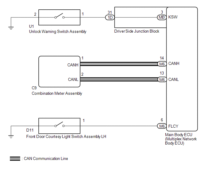
The key reminder warning buzzer sounds when the driver side door is opened while the ignition switch is in the LOCK or ACC positions. The key reminder warning buzzer is activated when the main body ECU (multiplex network body ECU) sends a key switch signal and driver side courtesy light switch signal to the combination meter.
WIRING DIAGRAM
CAUTION / NOTICE / HINT
HINT:
Since the key reminder warning system has functions that use CAN communication, first confirm that there is no malfunction in the communication system by inspecting the CAN communication functions in accordance with How to Proceed with Troubleshooting. Then conduct the following troubleshooting procedure.
PROCEDURE
|
1. |
READ VALUE USING TECHSTREAM (FL DOOR COURTESY) |
(a) Connect the Techstream to the DLC3.
(b) Turn the ignition switch ON (IG).
(c) Turn the Techstream on.
(d) Enter the following menus: Body Electrical / Main Body / Data List.
(e) According to the display on the Techstream, read the Data List.
Main Body|
Tester Display |
Measurement Item/Range |
Normal Condition |
Diagnostic Note |
|---|---|---|---|
|
FL Door Courtesy |
Front LH door courtesy light switch signal / ON or OFF |
ON: Front LH door closed OFF: Front LH door opened |
- |
OK:
When the front door courtesy light switch assembly LH is operated, the display changes as shown in the table.
| NG | .gif) |
GO TO LIGHTING SYSTEM (DOOR COURTESY LIGHT SWITCH CIRCUIT) |
|
.gif)
|
2. |
READ VALUE USING TECHSTREAM (KEY UNLOCK WARNING SW) |
(a) Connect the Techstream to the DLC3.
(b) Turn the ignition switch to ON (IG).
(c) Turn the Techstream on.
(d) Enter the following menus: Body Electrical / Main Body / Data List.
(e) According to the display on the Techstream, read the Data List.
Main Body|
Tester Display |
Measurement Item/Range |
Normal Condition |
Diagnostic Note |
|---|---|---|---|
|
Key Unlock Warning SW |
Unlock warning switch / OFF or ON |
OFF: Ignition key is not inserted ON: Ignition key is inserted |
- |
OK:
When the unlock warning switch is operated, the display changes as shown in the table.
| NG | |
GO TO STEP 4 |
|
|
3. |
CHECK COMBINATION METER ASSEMBLY (BUZZER OPERATION) |
(a) Remove the key from the key cylinder, turn the light control switch on the headlight dimmer switch assembly to the tail position, and open the driver door.
OK:
The light reminder warning buzzer sounds.
HINT:
The key reminder warning system sounds the buzzer built in to the combination meter for key reminder warnings. This buzzer is also used for the light reminder warning system. Therefore, check the operation of the combination meter buzzer by checking if the buzzer sounds to inform that the lights are still on.
| OK | |
REPLACE MAIN BODY ECU (MULTIPLEX NETWORK BODY ECU) |
| NG | |
REPLACE COMBINATION METER ASSEMBLY |
|
4. |
INSPECT UNLOCK WARNING SWITCH ASSEMBLY |
(a) Remove the unlock warning switch assembly (See page
.gif) ).
).
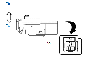
(b) Inspect the unlock warning switch assembly.
|
(1) Measure the resistance according to the value(s) in the table below. Text in Illustration
|
|
| NG | |
REPLACE UNLOCK WARNING SWITCH ASSEMBLY |
|
|
5. |
CHECK HARNESS AND CONNECTOR (DRIVER SIDE JUNCTION BLOCK - UNLOCK WARNING SWITCH ASSEMBLY) |
(a) Disconnect the U1 unlock warning switch and 1D driver side junction block connectors.
(b) Measure the resistance according to the value(s) in the table below.
Standard Resistance:
|
Tester Connection |
Condition |
Specified Condition |
|---|---|---|
|
U1-1 - 1D-31 |
Always |
Below 1 Ω |
|
U1-2 - Body ground |
Always |
Below 1 Ω |
|
U1-1 - Body ground |
Always |
10 kΩ or higher |
| NG | |
REPAIR OR REPLACE HARNESS OR CONNECTOR |
|
|
6. |
INSPECT DRIVER SIDE JUNCTION BLOCK |
(a) Remove the main body ECU (multiplex network body ECU) (See page
).
(b) Measure the resistance according to the value(s) in the table below.
|
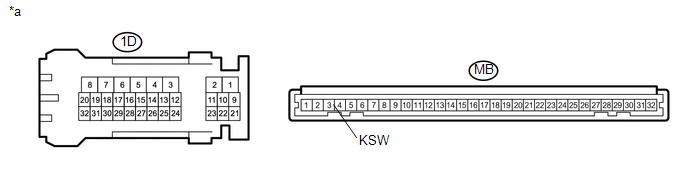
*a |
Component without harness connected (Driver Side Junction Block) |
- |
- |
Standard Resistance:
|
Tester Connection |
Condition |
Specified Condition |
|---|---|---|
|
MB-3 (KSW) - 1D-31 |
Always |
Below 1 Ω |
|
MB-3 (KSW) or 1D-31 - Body ground |
Always |
10 Ω or higher |
| OK | |
REPLACE MAIN BODY ECU (MULTIPLEX NETWORK BODY ECU) |
| NG | |
REPLACE DRIVER SIDE JUNCTION BLOCK |
 Terminals Of Ecu
TERMINALS OF ECU
1. CHECK MAIN BODY ECU (MULTIPLEX NETWORK BODY ECU) AND DRIVER SIDE JUNCTION
BLOCK
(a) Remove the main body ECU (multiplex network body ECU) from the driver side
junction bloc ...

Other materials:
Washer Level Warning Switch
Components
COMPONENTS
ILLUSTRATION
Inspection
INSPECTION
PROCEDURE
1. INSPECT LEVEL WARNING SWITCH ASSEMBLY
HINT:
This check should be performed with the windshield washer motor and pump assembly
installed on the washer jar.
(a) Fill the washer jar with washer fluid.
(b) ...
Installation
INSTALLATION
PROCEDURE
1. INSTALL TRANSFER POSITION SWITCH (for 4WD)
Click here
2. INSTALL ENGINE SWITCH
Click here
3. INSTALL AIR CONDITIONING CONTROL ASSEMBLY
(a) Connect the connectors.
(b) Engage the 8 clips to install the air conditioning control assembly.
4. INSTALL RADIO AND DISP ...
Cruise Main Indicator Light Circuit
DESCRIPTION
When the dynamic radar cruise control system is turned on using the cruise control
main switch (ON-OFF button), the cruise control indicator (vehicle-to-vehicle distance
control mode) illuminates. The ECM uses this and other indicators to indicate the
control condition (presence o ...
