Toyota Tacoma (2015-2018) Service Manual: ECU Power Source Circuit
DESCRIPTION
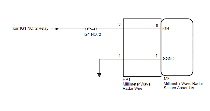
This circuit supplies power to the millimeter wave radar sensor assembly when the ignition switch is ON.
WIRING DIAGRAM
CAUTION / NOTICE / HINT
NOTICE:
Inspect the fuses for circuits related to this system before performing the following inspection procedure.
PROCEDURE
|
1. |
CHECK MILLIMETER WAVE RADAR SENSOR ASSEMBLY (B VOLTAGE) |
|
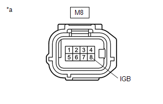
(a) Disconnect the millimeter wave radar sensor assembly connector. |
|
(b) Turn the ignition switch to ON.
(c) Measure the voltage according to the value(s) in the table below.
Standard Voltage:
|
Tester Connection |
Condition |
Specified Condition |
|---|---|---|
|
M8-8 (IGB) - Body ground |
Ignition switch ON |
11 to 14 V |
(d) Turn the ignition switch off.
(e) Connect the millimeter wave radar sensor assembly connector.
| NG | .gif) |
GO TO STEP 4 |
|
.gif)
|
2. |
CHECK HARNESS AND CONNECTOR (MILLIMETER WAVE RADAR SENSOR ASSEMBLY - BODY GROUND) |
|
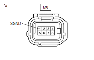
(a) Disconnect the millimeter wave radar sensor assembly connector. |
|
(b) Measure the resistance according to the value(s) in the table below.
Standard Resistance:
|
Tester Connection |
Condition |
Specified Condition |
|---|---|---|
|
M8-1 (SGND) - Body ground |
Always |
Below 1 Ω |
(c) Connect the millimeter wave radar sensor assembly connector.
| OK | |
PROCEED TO NEXT SUSPECTED AREA SHOWN IN PROBLEM SYMPTOMS TABLE |
|
|
3. |
CHECK MILLIMETER WAVE RADAR WIRE |
(a) Disconnect the M8 millimeter wave radar sensor assembly connector.
(b) Disconnect the EP1 millimeter wave radar wire connector.
(c) Measure the resistance according to the value(s) in the table below.
Standard Resistance:
|
Tester Connection |
Condition |
Specified Condition |
|---|---|---|
|
M8-1 (SGND) - EP1-1 |
Always |
Below 1 Ω |
(d) Connect the M8 millimeter wave radar sensor assembly connector.
(e) Connect the EP1 millimeter wave radar wire connector.
| OK | |
REPAIR OR REPLACE HARNESS OR CONNECTOR |
| NG | |
REPAIR MILLIMETER WAVE RADAR WIRE |
|
4. |
CHECK MILLIMETER WAVE RADAR WIRE |
(a) Disconnect the M8 millimeter wave radar sensor assembly connector.
(b) Disconnect the EP1 millimeter wave radar wire connector.
(c) Measure the resistance according to the value(s) in the table below.
Standard Resistance:
|
Tester Connection |
Condition |
Specified Condition |
|---|---|---|
|
M8-8 (IGB) - EP1-8 |
Always |
Below 1 Ω |
|
EP1-8 - EP1-1 |
Always |
10 kΩ or higher |
(d) Connect the M8 millimeter wave radar assembly connector.
(e) Connect the EP1 millimeter wave radar sensor wire connector.
| OK | |
REPAIR OR REPLACE HARNESS OR CONNECTOR (POWER SOURCE CIRCUIT) |
| NG | |
REPAIR MILLIMETER WAVE RADAR WIRE |
 Front Radar Sensor (C1A10)
DESCRIPTION
When an internal malfunction is detected in the millimeter wave radar sensor
assembly, DTC C1A10 is stored.
DTC No.
Detection Item
DTC Detection Condit ...
 Pre-collision System Warning Buzzer
Components
COMPONENTS
ILLUSTRATION
*1
SKID CONTROL BUZZER
-
-
Inspection
INSPECTION
PROCEDURE
1. INSPECT SKID CONTROL BUZZER
...
Other materials:
Diagnostic Trouble Code Chart
DIAGNOSTIC TROUBLE CODE CHART
VSC System
DTC Code
Detection Item
See page
C1201
Engine Control System Malfunction
C1203
ECM Communication Circuit Malfunction
C120B
...
Removal
REMOVAL
PROCEDURE
1. REMOVE FRONT WHEEL
2. REMOVE REAR WHEEL
3. REMOVE TIRE PRESSURE WARNING VALVE AND TRANSMITTER
(a) Remove the cap and valve core to release the air from the tire.
NOTICE:
Keep the removed cap and valve core.
(b) After ensuring that a sufficient amount of air has been rele ...
Fail-safe Chart
FAIL-SAFE CHART
1. Fail-safe
This function minimizes the loss of operation when any abnormality occurs in
a sensor or solenoid.
Fail-safe Control List
Malfunction Part
Function
Transmission revolution sensor (NT)
During a transmission revolutio ...
