Toyota Tacoma (2015-2018) Service Manual: Terminals Of Ecu
TERMINALS OF ECU
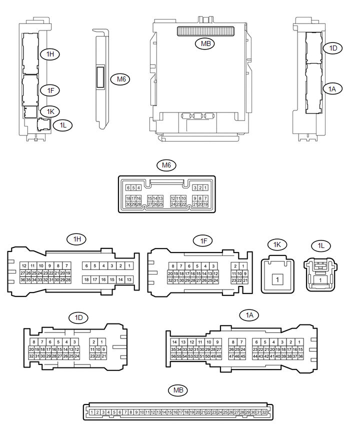
1. CHECK MAIN BODY ECU (MULTIPLEX NETWORK BODY ECU) AND DRIVER SIDE JUNCTION BLOCK
(a) Remove the main body ECU (multiplex network body ECU) from the driver side
junction block (See page .gif) ).
).
(b) Disconnect the 1D driver side junction block connector.
(c) Measure the voltage and resistance according to the value(s) in the table below.
|
Terminal No. (Symbol) |
Wiring Color |
Terminal Description |
Condition |
Specified Condition |
|---|---|---|---|---|
|
MB-11 (GND1) - Body ground |
None - Body ground |
Ground |
Always |
Below 1 Ω |
|
MB-31 (BECU) - Body ground |
None - Body ground |
Battery power supply |
Always |
11 to 14 V |
|
MB-30 (ACC) - Body ground |
None - Body ground |
ACC power supply |
Ignition switch ON(ACC) |
11 to 14 V |
|
MB-32 (IG) - Body ground |
None - Body ground |
Ignition switch power supply |
Ignition switch ON(IG) |
11 to 14 V |
|
1D-31 (KSW) - Body ground |
G - Body ground |
Unlock warning switch input |
No Key in ignition key cylinder (off) |
10 kΩ or higher |
|
Key inserted ignition key cylinder (on) |
Below 1 Ω |
(d) Install the main body ECU (multiplex network body ECU) to the driver side
junction block (See page ).
(e) Reconnect the 1D driver side junction block connector.
(f) Measure the voltage and check for pulse according to the value(s) in the table below.
|
Terminal No. (Symbol) |
Wiring Color |
Terminal Description |
Condition |
Specified Condition |
|---|---|---|---|---|
|
M6-6 (FLCY) - Body ground |
Y - Body ground |
Front door LH courtesy light switch input |
Front door LH open |
Below 1 V |
|
Front door LH closed |
Pulse generation |
|||
|
1D-31 (KSW) - Body ground |
G - Body ground |
Unlock warning switch input |
No Key in ignition key cylinder (off) |
11 to 14 V |
|
Key inserted ignition key cylinder (on) |
Below 1 V |
 Diagnosis System
DIAGNOSIS SYSTEM
1. CHECK DLC3
(a) Check the DLC3 (See page ).
2. INSPECT BATTERY VOLTAGE
(a) Measure the battery voltage.
Standard voltage:
11 to 14 V
If the voltage is below 11 V, replace t ...
 Key Reminder Buzzer does not Sound
DESCRIPTION
The key reminder warning buzzer sounds when the driver side door is opened while
the ignition switch is in the LOCK or ACC positions. The key reminder warning buzzer
is activated when ...
Other materials:
Data List / Active Test
DATA LIST / ACTIVE TEST
HINT:
By accessing the Data List displayed by the Techstream, you can check values
of switches and sensors without removing any parts. Reading the Data List as the
first step of troubleshooting is one method to shorten diagnostic time.
1. DATA LIST FOR OCCUPANT DETECTI ...
Diagnosis System
DIAGNOSIS SYSTEM
1. CHECK DLC3
(a) The vehicle's ECU uses the ISO 9141-2 for communication protocol. The terminal
arrangement of the DLC3 complies with SAE J1962 and matches the ISO 15765-4 format.
Symbols (Terminal No.)
Terminal Description
Condition
...
Crawl Switch
Components
COMPONENTS
ILLUSTRATION
Inspection
INSPECTION
PROCEDURE
1. INSPECT CRAWL CONTROL SWITCH (DRIVE MONITOR SWITCH)
(a) Check the resistance.
(1) Measure the resistance according to the value(s) in the table below.
Text in Illustration
*1
Crawl Control Sw ...
