Toyota Tacoma (2015-2018) Service Manual: Stereo Component Amplifier Disconnected (B15D3)
DESCRIPTION
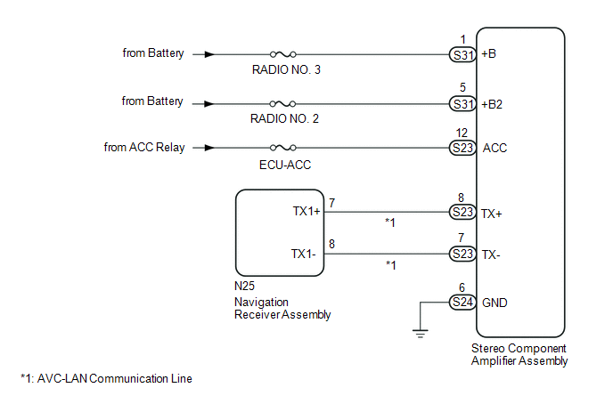
The navigation receiver assembly and stereo component amplifier assembly are connected by the AVC-LAN communication line.
When an AVC-LAN communication error occurs between the navigation receiver assembly and stereo component amplifier assembly, this DTC will be stored.
|
DTC No. |
DTC Detection Condition |
Trouble Area |
|---|---|---|
|
B15D3*1 |
When either condition below is met:
|
|
HINT:
- *1: Even if no fault is present, this DTC may be stored depending on the battery condition or engine start voltage.
- The navigation receiver assembly is the master unit.
WIRING DIAGRAM
CAUTION / NOTICE / HINT
NOTICE:
Inspect the fuses for circuits related to this system before performing the following inspection procedure.
PROCEDURE
|
1. |
CHECK DTC |
(a) If DTC B15C3 is output, perform the troubleshooting of DTC B15C3 first.
Result|
Result |
Proceed to |
|---|---|
|
DTC B15C3 is not output |
A |
|
DTC B15C3 is output |
B |
| B | .gif) |
GO TO DTC "B15C3" IN DIAGNOSTIC TROUBLE CODE CHART |
|
.gif)
|
2. |
CHECK OPTIONAL COMPONENTS (INCLUDING ASSOCIATED WIRING) |
(a) Check that optional components (including associated wiring) which generate radio waves are not installed.
Result|
Result |
Proceed to |
|---|---|
|
Optional components (including associated wiring) are installed. |
A |
|
Optional components (including associated wiring) are not installed. |
B |
HINT:
- Electrical noise from radio waves generated by optional components or the wiring for those components may affect AVC-LAN communication.
- This DTC may be stored when an AVC-LAN communication error occurs due to electrical noise.
| B | |
GO TO STEP 4 |
|
|
3. |
REMOVE OPTIONAL COMPONENTS (INCLUDING ASSOCIATED WIRING) |
(a) Remove optional components (including associated wiring).
NOTICE:
Do not remove optional components or associated wiring without the permission of the customer.
|
|
4. |
CHECK DTC |
(a) Clear the DTCs (See page .gif) ).
).
(b) Recheck for DTCs and check if the same DTC is output again.
OK:
No DTCs are output.
| OK | |
END |
|
|
5. |
CHECK HARNESS AND CONNECTOR (STEREO COMPONENT AMPLIFIER ASSEMBLY POWER SOURCE) |
|
(a) Disconnect the stereo component amplifier assembly connectors. |
|
(b) Measure the resistance according to the value(s) in the table below.
Standard Resistance:
|
Tester Connection |
Condition |
Specified Condition |
|---|---|---|
|
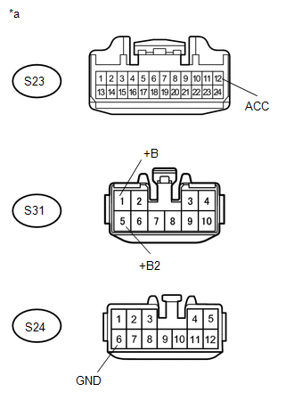
S24-6 (GND) - Body ground |
Always |
Below 1 Ω |
(c) Measure the voltage according to the value(s) in the table below.
Standard Voltage:
|
Tester Connection |
Switch Condition |
Specified Condition |
|---|---|---|
|
S31-1 (+B) - S24-6 (GND) |
Always |
11 to 14 V |
|
S31-5 (+B2) - S24-6 (GND) |
Always |
11 to 14 V |
|
S23-12 (ACC) - S24-6 (GND) |
Ignition switch ACC |
11 to 14 V |
|
*a |
Front view of wire harness connector (to Stereo Component Amplifier Assembly) |
| NG | |
REPAIR OR REPLACE HARNESS OR CONNECTOR |
|
|
6. |
CHECK HARNESS AND CONNECTOR (NAVIGATION RECEIVER ASSEMBLY - STEREO COMPONENT AMPLIFIER ASSEMBLY) |
(a) Disconnect the N25 navigation receiver assembly connector.
(b) Disconnect the S23 stereo component amplifier assembly connector.
(c) Measure the resistance according to the value(s) in the table below.
Standard Resistance:
|
Tester Connection |
Condition |
Specified Condition |
|---|---|---|
|
N25-7 (TX1+) - S23-8 (TX+) |
Always |
Below 1 Ω |
|
N25-8 (TX1-) - S23-7 (TX-) |
Always |
Below 1 Ω |
|
N25-7 (TX1+) - Body ground |
Always |
10 kΩ or higher |
|
N25-8 (TX1-) - Body ground |
Always |
10 kΩ or higher |
| NG | |
REPAIR OR REPLACE HARNESS OR CONNECTOR |
|
|
7. |
REPLACE STEREO COMPONENT AMPLIFIER ASSEMBLY |
(a) Replace the stereo component amplifier assembly (See page
).
(b) Clear the DTCs (See page ).
(c) Recheck for DTCs and check if the same DTC is output again.
OK:
No DTCs are output.
| OK | |
END |
| NG | |
REPLACE NAVIGATION RECEIVER ASSEMBLY |
 Sending Malfunction (Navigation to APGS) (U0073,U0100,U0129,U0140,U0155,U0164)
DESCRIPTION
These DTCs are stored when a malfunction occurs in the CAN communication circuit.
DTC Code
DTC Detection Condition
Trouble Area
U0073
...
 Voice Recognition Microphone Disconnected (B1579)
DESCRIPTION
The navigation receiver assembly and telephone microphone assembly are connected
to each other using the microphone connection detection signal lines.
This DTC is stored when the micro ...
Other materials:
Illumination for Panel Switch does not Come on with Tail Switch ON
PROCEDURE
1.
CHECK VEHICLE SIGNAL (OPERATION CHECK)
(a) Enter the "Vehicle Signal Check Mode" screen. Refer to Check Vehicle Signal
in Operation Check (See page ).
(b) Check that the display changes between ON and OFF according to the light
control ...
Removal
REMOVAL
PROCEDURE
1. REMOVE LOWER STEERING COLUMN COVER
2. REMOVE UPPER STEERING COLUMN COVER
3. REMOVE WINDSHIELD WIPER SWITCH ASSEMBLY
(a) Disconnect the 2 connectors.
Text in Illustration
*a
Protective Tape
...
Stop Light Switch OFF Stuck Malfunction (C1426)
DESCRIPTION
The skid control ECU (brake actuator assembly) inputs the stop light signal and
brake operation condition. When the brake pedal is depressed and the stop light
switch signal is not input, C1426 is output.
DTC No.
Detection Item
DTC Detection Conditi ...
