Toyota Tacoma (2015-2018) Service Manual: Interior Light Circuit
DESCRIPTION
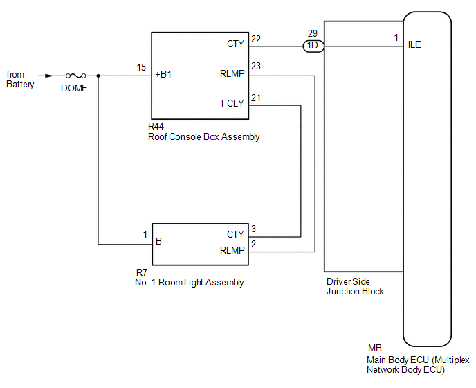
The illuminated entry system controls the interior lights.
WIRING DIAGRAM
CAUTION / NOTICE / HINT
NOTICE:
- Inspect the fuses for circuits related to this system before performing the following inspection procedure.
- If the main body ECU (multiplex network body ECU) is replaced, refer
to Registration (See page
.gif) ).*1
).*1
- *1: w/ Smart Key System
PROCEDURE
|
1. |
PERFORM ACTIVE TEST USING TECHSTREAM (ILLUMINATED ENTRY SYSTEM) |
(a) Connect the Techstream to the DLC3.
(b) Turn the ignition switch to ON.
(c) Turn the Techstream on.
(d) Enter the following menus: Body Electrical / Main Body / Active Test.
(e) Perform the Active Test according to the display on the Techstream.
Main Body|
Tester Display |
Test Part |
Control Range |
Diagnostic Note |
|---|---|---|---|
|
Illuminated Entry System |
Interior lights |
ON/OFF |
Interior light door switch on and all doors closed |
OK:
Each light fades in.
| OK | .gif) |
PROCEED TO NEXT SUSPECTED AREA SHOWN IN PROBLEM SYMPTOMS TABLE |
|
.gif)
|
2. |
CHECK HARNESS AND CONNECTOR (BATTERY - DRIVER SIDE JUNCTION BLOCK) |
|
(a) Disconnect the driver side junction block connector. |
|
(b) Measure the voltage according to the value(s) in the table below.
Standard Voltage:
|
Tester Connection |
Switch Condition |
Specified Condition |
|---|---|---|
|
1D-29 - Body ground |
Interior light switch in DOOR position |
11 to 14 V |
|
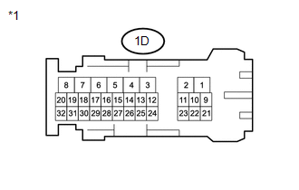
*1 |
Front view of wire harness connector (to Driver Side Junction Block) |
| NG | |
REPAIR OR REPLACE HARNESS OR CONNECTOR |
|
|
3. |
INSPECT DRIVER SIDE JUNCTION BLOCK |
|
(a) Remove the driver side junction block. |
|
(b) Measure the resistance according to the value(s) in the table below.
Standard Resistance:
|
Tester Connection |
Condition |
Specified Condition |
|---|---|---|
|
1D-29 - MB-1 (ILE) |
Always |
Below 1 Ω |
|
MB-1 (ILE) - Body ground |
Always |
10 kΩ or higher |
|
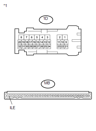
*1 |
Component without harness connected (Driver Side Junction Block) |
| OK | |
REPLACE MAIN BODY ECU (MULTIPLEX NETWORK BODY ECU) |
| NG | |
REPLACE DRIVER SIDE JUNCTION BLOCK |
 Interior Light Auto Cut Circuit
DESCRIPTION
When the battery saving control operates, the main body ECU (multiplex network
body ECU) controls the operation of the DOME CUT relay, that is built in to the
driver side junction blo ...
 Engine Switch Illumination Circuit
DESCRIPTION
The illuminated entry system controls the engine switch illumination.
WIRING DIAGRAM
PROCEDURE
1.
READ VALUE USING TECHSTREAM (POWER/ENGINE SW LIGHT)
...
Other materials:
Reassembly
REASSEMBLY
PROCEDURE
1. INSPECT CENTER NO. 2 SUPPORT BEARING ASSEMBLY
(a) When turning the center No. 2 support bearing assembly with your hand, check
that it turns smoothly without catching and that there are no cracks or damage.
If there are any defects, replace it.
2. INSTALL CENTER NO. ...
Dtc Check / Clear
DTC CHECK / CLEAR
1. CHECK FOR TRANSPONDER KEY ECU ASSEMBLY DTC
(a) Connect the Techstream to the DLC3.
(b) Turn the ignition switch to ON.
(c) Turn the Techstream on.
(d) Enter the following menus: Body Electrical / Immobiliser / Trouble Codes.
(e) Check the details of the DTC(s) (See page
...
Removal
REMOVAL
PROCEDURE
1. PRECAUTION
NOTICE:
After turning the ignition switch off, waiting time may be required before disconnecting
the cable from the negative (-) battery terminal. Therefore, make sure to read the
disconnecting the cable from the negative (-) battery terminal notices before pr ...
