Toyota Tacoma (2015-2018) Service Manual: Engine Switch Illumination Circuit
DESCRIPTION
The illuminated entry system controls the engine switch illumination.
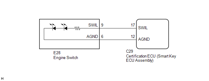
WIRING DIAGRAM
PROCEDURE
|
1. |
READ VALUE USING TECHSTREAM (POWER/ENGINE SW LIGHT) |
(a) Connect the Techstream to the DLC3.
(b) Turn the engine switch to ON.
(c) Turn the Techstream on.
(d) Enter the following menus: Body Electrical / Smart Key / Active Test.
(e) Perform the Active Test according to the display on the Techstream.
Smart Key|
Tester Display |
Test Part |
Control Range |
Diagnostic Note |
|---|---|---|---|
|
Power/Engine SW Light |
Engine switch illumination |
OFF/ON |
When performing this Active Test, make sure the following condition is met: The engine switch illumination is off (15 seconds or more have elapsed since it turned from on to off) and the engine switch is on (ACC) or on (IG), or the engine is running. |
OK:
Engine switch illumination comes on.
| OK | .gif) |
PROCEED TO NEXT SUSPECTED AREA SHOWN IN PROBLEM SYMPTOMS TABLE |
|
.gif)
|
2. |
INSPECT ENGINE SWITCH |
(a) Remove the engine switch.
- for 2TR-FE (See page
.gif) )
) - for 2GR-FKS (See page )
(b) Inspect the engine switch.
- for 2TR-FE (See page )
- for 2GR-FKS (See page )
OK:
Engine switch illumination is normal.
Result|
Result |
Proceed to |
|---|---|
|
OK |
A |
|
NG (for 2TR-FE) |
B |
|
NG (for 2GR-FKS) |
C |
| B | |
REPLACE ENGINE SWITCH |
| C | |
REPLACE ENGINE SWITCH |
|
|
3. |
CHECK HARNESS AND CONNECTOR (ENGINE SWITCH - CERTIFICATION ECU (SMART KEY ECU ASSEMBLY)) |
(a) Disconnect the C29 certification ECU (smart key ECU assembly) connector.
(b) Disconnect the E28 engine switch connector.
(c) Measure the resistance according to the value(s) in the table below.
Standard Resistance:
|
Tester Connection |
Condition |
Specified Condition |
|---|---|---|
|
E28-9 (SWIL) - C29-17 (SWIL) |
Always |
Below 1 Ω |
|
E28-6 (AGND) - C29-12 (AGND) |
Always |
Below 1 Ω |
|
E28-9 (SWIL) - Body ground |
Always |
10 kΩ or higher |
|
E28-6 (AGND) - Body ground |
Always |
10 kΩ or higher |
| OK | |
REPLACE CERTIFICATION ECU (SMART KEY ECU ASSEMBLY) |
| NG | |
REPAIR OR REPLACE HARNESS OR CONNECTOR |
 Interior Light Circuit
DESCRIPTION
The illuminated entry system controls the interior lights.
WIRING DIAGRAM
CAUTION / NOTICE / HINT
NOTICE:
Inspect the fuses for circuits related to this system before perfor ...
 Taillight Relay Circuit
DESCRIPTION
The main body ECU (multiplex network body ECU) controls the operation of the
TAIL relay.
WIRING DIAGRAM
CAUTION / NOTICE / HINT
NOTICE:
Inspect the fuses for circuits rela ...
Other materials:
Dtc Check / Clear
DTC CHECK / CLEAR
1. CHECK DTC (for TIRE PRESSURE WARNING ECU AND RECEIVER) (USING TECHSTREAM)
(a) Turn the ignition switch off.
(b) Connect the Techstream to the DLC3.
(c) Turn the ignition switch to ON.
(d) Turn the Techstream on.
(e) Enter the following menus: Chassis / Tire Pressure Monito ...
Installation
INSTALLATION
PROCEDURE
1. INSTALL OIL COOLER TUBE
(a) Install the oil cooler tube to the vehicle body with the 2 bolts.
Torque:
28 N·m {286 kgf·cm, 21 ft·lbf}
2. INSTALL NO. 4 OIL COOLER INLET HOSE AND NO. 4 OIL COOLER OUTLET HOSE
NOTICE:
When connecting the hoses to the tube, su ...
Air Fuel Ratio Sensor
Components
COMPONENTS
ILLUSTRATION
Removal
REMOVAL
PROCEDURE
1. REMOVE AIR FUEL RATIO SENSOR (for Bank 1 Sensor 1)
(a) Disconnect the air fuel ratio sensor connector.
(b) Disengage the clamp to separate the air fuel ratio sensor wire ...
