Toyota Tacoma (2015-2018) Service Manual: On-vehicle Inspection
ON-VEHICLE INSPECTION
PROCEDURE
1. CHECK FUEL PUMP OPERATION AND INSPECT FOR FUEL LEAK
(a) Connect the Techstream to the DLC3.
(1) Turn the ignition switch to ON.
NOTICE:
Do not start the engine.
(2) Turn the Techstream on.
(3) Enter the following menus: Powertrain / Engine / Active Test / Control the Fuel Pump / Speed.
(b) Check the fuel pump operation.
(1) Check for pressure in the fuel inlet tube from the fuel line. Check that the sound of fuel flowing in the fuel tank can be heard.
If there is no sound, check the fuel pump, ECM and wiring connector.
(c) Inspect for fuel leaks.
(1) Check that there are no fuel leaks anywhere in the system after performing maintenance.
If there is a fuel leak, repair or replace parts as necessary.
2. CHECK FUEL PRESSURE
(a) Check the battery voltage.
Click here .gif)
(b) Discharge the fuel system pressure.
Click here
(c) Disconnect the cable from the negative (-) battery terminal.
NOTICE:
- After turning the ignition switch off, waiting time may be required
before disconnecting the cable from the battery terminal. Therefore, make
sure to read the disconnecting the cable from the battery terminal notice
before proceeding with work.
Click here
- When disconnecting the cable, some systems need to be initialized after
the cable is reconnected.
Click here
(d) Disconnect the fuel tube sub-assembly (Direct injection side).
Click here
(e) Disconnect the fuel tube sub-assembly (Port injection side).
Click here
|
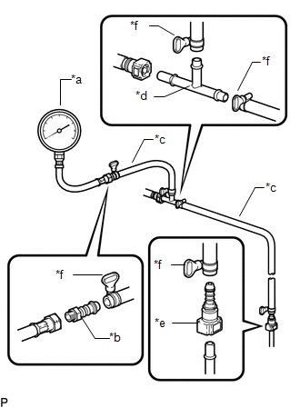
(f) Install SST (pressure gauge) as shown in the illustration. SST: 09268-45100 09268-41250 09268-41260 09268-41270 95336-08070 SST: 09268-31014 09268-41500 09268-41700 Text in Illustration
|
|
(g) Wipe off any gasoline.
(h) Reconnect the cable to the negative (-) battery terminal.
NOTICE:
When disconnecting the cable, some systems need to be initialized after the cable is reconnected.
Click here
(i) Operate the fuel pump.
(1) Connect the Techstream to the DLC3.
(2) Turn the ignition switch to ON.
NOTICE:
Do not start the engine.
(3) Turn the Techstream on.
(4) Enter the following menus: Powertrain / Engine / Active Test / Control the Fuel Pump / Speed.
(j) Measure the fuel pressure.
Standard fuel pressure:
196 to 588 kPa (2.0 to 6.0 kgf/cm2, 28 to 85 psi)
If the fuel pressure is higher than the specification, replace the fuel main valve assembly.
If the pressure is less than the specification, check the fuel hoses, connections, fuel filter assembly, fuel main valve assembly, and fuel pump.
(k) Start the engine.
(l) Measure the fuel pressure at idle.
Standard fuel pressure:
196 to 588 kPa (2.0 to 6.0 kgf/cm2, 28 to 85 psi)
If the pressure is not as specified, check the fuel pump, fuel main valve assembly and fuel injector assembly.
(m) Stop the engine.
(n) Check that the fuel pressure remains as specified for 5 minutes after the engine has stopped.
Standard fuel pressure:
147 kPa (1.5 kgf/cm2, 21 psi) or more
If the pressure is not as specified, check the fuel pump, fuel main valve assembly or fuel injector assembly.
(o) After checking the fuel pressure, disconnect the cable from the negative (-) battery terminal and carefully remove SST and the fuel tube connector to prevent fuel from spilling.
(p) Reconnect the fuel tube sub-assembly.
Click here
(q) Inspect for fuel leaks (Step 1).
3. CHECK FUEL PRESSURE (for High Pressure)
(a) Connect the Techstream to the DLC3.
(1) Turn the ignition switch to ON.
(2) Turn the Techstream on.
(b) Start and warm up the engine.
(c) Run the engine at idle.
(d) Enter the following menus: Powertrain / Engine / Data List / Fuel Press.
(e) Check the high pressure side fuel pressure.
Standard fuel pressure:
1800 to 2800 kPa (18.4 to 28.6 kgf/cm2, 261 to 406 psi)
If the pressure is not as specified, check the fuel pump, fuel pump assembly, fuel pressure sensor and wire harness.
(f) Stop the engine.
 System Diagram
SYSTEM DIAGRAM
1. HIGH PRESSURE SIDE FUEL SYSTEM WIRING DIAGRAM
2. LOW PRESSURE SIDE FUEL SYSTEM WIRING DIAGRAM
...
 Fuel Tank
...
Other materials:
Cargo and luggage
Take notice of the following information about storage precautions, cargo
capacity and load.
● Stow cargo and luggage in the rear deck whenever possible.
● Be sure all items are secured in place.
● Be careful to keep the vehicle level. Placing the weight as far forward as
po ...
Removal
REMOVAL
PROCEDURE
1. DRAIN DIFFERENTIAL OIL
2. REMOVE PROPELLER WITH CENTER BEARING SHAFT ASSEMBLY (for 2WD)
3. REMOVE PROPELLER WITH CENTER BEARING SHAFT ASSEMBLY (for 4WD)
4. REMOVE REAR DRIVE PINION NUT
(a) Using SST and a hammer, unstake the nut.
SST: 09930-00010
(b) for BD20:
...
On-vehicle Inspection
ON-VEHICLE INSPECTION
PROCEDURE
1. INSPECT REFRIGERANT PRESSURE
(a) This method uses a refrigerant recovery unit set to locate problem areas.
Read the refrigerant pressure when the test conditions are established.
Test conditions:
Temperature at the air inlet with the air recirculation ...
