Toyota Tacoma (2015-2018) Service Manual: Installation
INSTALLATION
PROCEDURE
1. INSTALL INTAKE MANIFOLD
|
(a) Set 2 new No. 1 intake manifold to head gaskets on cylinder head sub-assembly and cylinder head LH as shown in the illustration. NOTICE:
|
|
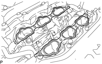
(b) Set the intake manifold on the cylinder head sub-assembly and cylinder head LH.
(c) Install and uniformly tighten the 4 bolts and 4 nuts.
Torque:
21 N·m {214 kgf·cm, 15 ft·lbf}
2. INSTALL FUEL DELIVERY PIPE SUB-ASSEMBLY
Click here .gif)
3. CONNECT ENGINE WIRE
Click here
4. CONNECT NO. 2 FUEL TUBE SUB-ASSEMBLY
Click here
5. INSTALL INTAKE AIR SURGE TANK ASSEMBLY
(a) Install a new air surge tank to intake manifold gasket to the intake air surge tank assembly.
(b) Set the intake air surge tank assembly on the intake manifold.
(c) Install and uniformly tighten the 5 bolts and 2 nuts.
Torque:
21 N·m {214 kgf·cm, 15 ft·lbf}
(d) Connect the PCV hose to the intake air surge tank assembly, and slide the clip to secure the hose.
(e) Connect the intake air control valve actuator connector to the intake air control valve actuator.
(f) Engage the clamp to install the heater hose to the intake air surge tank assembly.
(g) Engage the clamp to connect the No. 1 fuel pipe sub-assembly and No. 2 fuel pipe sub-assembly.
(h) Connect the fuel vapor feed hose to the purge VSV, and slide the clamp to secure the hose.
(i) Engage the clamp to install the fuel vapor feed hose to the intake air surge tank assembly.
(j) Engage the 2 clamps to install the wire harness to the intake surge tank.
(k) Connect the purge VSV connector to the purge VSV.
(l) Connect the No. 4 water by-pass hose and No. 5 water by-pass hose to the throttle body with motor assembly, and slide the 2 clips to secure the No. 4 water by-pass hose and No. 5 water by-pass hose.
(m) Connect the throttle body with motor connector.
6. INSTALL THROTTLE BODY BRACKET
(a) Install the throttle body bracket to the timing chain cover assembly and intake air surge tank assembly with the 2 bolts.
Torque:
21 N·m {214 kgf·cm, 15 ft·lbf}
7. INSTALL NO. 1 SURGE TANK STAY
(a) Install the No. 1 surge tank stay to the cylinder head LH and intake air surge tank assembly with the 2 bolts.
Torque:
21 N·m {214 kgf·cm, 15 ft·lbf}
8. INSTALL NO. 2 SURGE TANK STAY
(a) Install the No. 2 surge tank stay to the cylinder head LH and intake air surge tank assembly with the 2 bolts.
Torque:
21 N·m {214 kgf·cm, 15 ft·lbf}
9. INSTALL AIR CLEANER CAP SUB-ASSEMBLY WITH NO. 1 AIR CLEANER HOSE
Click here
10. INSTALL NO. 1 V-BANK COVER BRACKET
(a) Install the No. 1 V-bank cover bracket to the intake air surge tank assembly with the 2 bolts.
Torque:
10 N·m {102 kgf·cm, 7 ft·lbf}
11. INSTALL V-BANK COVER SUB-ASSEMBLY
|
(a) Engage the 2 guides to install the V-bank cover sub-assembly. Text in Illustration
|
|
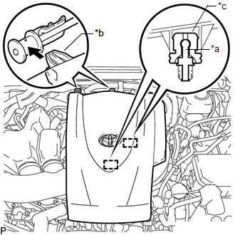
(b) Engage the 2 pins.
12. CONNECT CABLE TO NEGATIVE BATTERY TERMINAL
Torque:
5.4 N·m {55 kgf·cm, 48 in·lbf}
NOTICE:
When disconnecting the cable, some systems need to be initialized after the cable is reconnected.
Click here
13. ADD ENGINE COOLANT
Click here
14. INSPECT FOR COOLANT LEAK
Click here
15. INSPECT FOR FUEL LEAK
Click here
16. INSTALL NO. 1 ENGINE UNDER COVER SUB-ASSEMBLY
Torque:
30 N·m {306 kgf·cm, 22 ft·lbf}
17. INSTALL NO. 2 ENGINE UNDER COVER SUB-ASSEMBLY
Torque:
30 N·m {306 kgf·cm, 22 ft·lbf}
 Components
COMPONENTS
ILLUSTRATION
ILLUSTRATION
ILLUSTRATION
...
 Removal
REMOVAL
PROCEDURE
1. PRECAUTION
NOTICE:
After turning the ignition switch off, waiting time may be required before disconnecting
the cable from the negative (-) battery terminal. Therefore, make ...
Other materials:
Installation
INSTALLATION
PROCEDURE
1. INSTALL ENGINE COOLANT TEMPERATURE SENSOR
2. INSTALL ENGINE OIL PRESSURE SWITCH ASSEMBLY
3. INSTALL IGNITION COIL ASSEMBLY
4. INSTALL FUEL INJECTOR SEAL
5. INSTALL FUEL INJECTOR ASSEMBLY
6. INSTALL FUEL DELIVERY PIPE RH
7. INSTALL FUEL DELIVERY PIP ...
Multi-terrain Select Switch
Components
COMPONENTS
ILLUSTRATION
Removal
REMOVAL
PROCEDURE
1. REMOVE MULTI-TERRAIN SELECT SWITCH (DRIVE MONITOR SWITCH)
(a) Disengage the 2 claws to remove the multi-terrain select switch (drive
monitor switch).
Inspection ...
Diagnostic Trouble Code Chart
DIAGNOSTIC TROUBLE CODE CHART
HINT:
If a trouble code is displayed during the DTC check, inspect the trouble areas
listed for that code. For details of the code, refer to the "See page" below.
Seat Heater System
DTC Code
Detection Item
See page
...
