Toyota Tacoma (2015-2018) Service Manual: Components
COMPONENTS
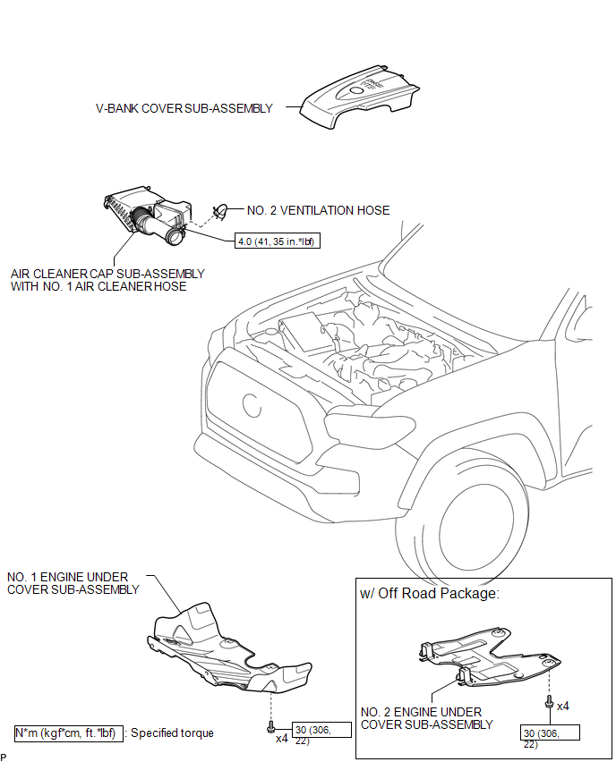
ILLUSTRATION
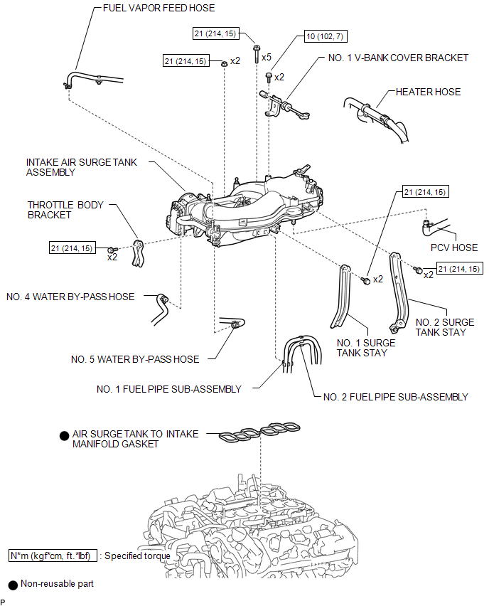
ILLUSTRATION
ILLUSTRATION
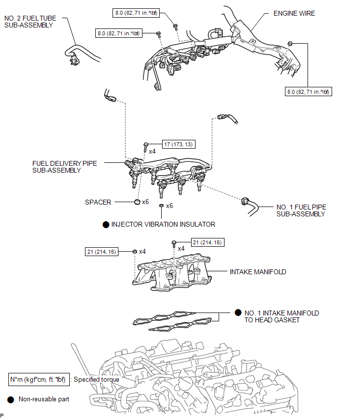
 Intake Manifold
...
 Installation
INSTALLATION
PROCEDURE
1. INSTALL INTAKE MANIFOLD
(a) Set 2 new No. 1 intake manifold to head gaskets on cylinder head
sub-assembly and cylinder head LH as shown in the illustration. ...
Other materials:
Data List / Active Test
DATA LIST / ACTIVE TEST
1. DATA LIST
HINT:
Using the Techstream to read the Data List allows the values or states of switches,
sensors, actuators and other items to be read without removing any parts. This non-intrusive
inspection can be very useful because intermittent conditions or signals ...
Removal
REMOVAL
PROCEDURE
1. PLACE FRONT WHEELS FACING STRAIGHT AHEAD
2. REMOVE FRONT WHEELS
3. REMOVE FRONT UPPER FENDER APRON SEAL
Click here
4. REMOVE NO. 2 ENGINE UNDER COVER SUB-ASSEMBLY (w/ Off Road Package)
5. REMOVE NO. 1 ENGINE UNDER COVER SUB-ASSEMBLY
6. REMOVE FRONT DIFFERENTIAL CARRI ...
While Alarm is Armed, Battery is Reconnected but Alarm does not Sound
DESCRIPTION
While the alarm is armed, the EEPROM inside the main body ECU (multiplex network
body ECU) will remember the armed state even if the battery is disconnected, and
the alarm will sound when the battery is reconnected.
If the alarm does not sound when the battery is reconnected, the a ...
