Toyota Tacoma (2015-2018) Service Manual: Installation
INSTALLATION
PROCEDURE
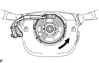
1. INSTALL SPIRAL CABLE SUB-ASSEMBLY WITH SENSOR
|
(a) Check that the ignition switch is off. |
|
(b) Check that the battery negative (-) terminal is disconnected.
CAUTION:
Wait at least 90 seconds after disconnecting the cable from the negative (-) battery terminal to prevent airbag and seat belt pretensioner activation.
(c) Confirm that the front tires face straight forward.
(d) Engage the 3 claws and install the spiral cable sub-assembly with sensor.
NOTICE:
When replacing the spiral cable sub-assembly with sensor with a new one, remove the lock pin before installing the steering wheel.
(e) Connect the connectors to the spiral cable sub-assembly with sensor.
NOTICE:
When handling the airbag connector, take care not to damage the airbag wire harness.
2. REMOVE UPPER STEERING COLUMN COVER
.gif)
3. INSTALL LOWER STEERING COLUMN COVER
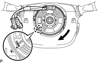
4. ADJUST SPIRAL CABLE
(a) Rotate the spiral cable sub-assembly with sensor counterclockwise slowly by hand until it feels firm.
NOTICE:
Do not turn the spiral cable sub-assembly with sensor by the airbag wire harness.
|
(b) Rotate the spiral cable sub-assembly with sensor clockwise approximately 2.5 turns to align the marks. NOTICE: Do not turn the spiral cable sub-assembly with sensor by the airbag wire harness. HINT: The spiral cable sub-assembly withy sensor will rotate approximately 2.5 turns to both the left and right from the center. |
|
5. INSTALL STEERING WHEEL ASSEMBLY
6. INSTALL STEERING PAD
(See page )
7. INSPECT STEERING PAD
8. INSPECT SRS WARNING LIGHT
(See page )
 Components
COMPONENTS
ILLUSTRATION
...
 Removal
REMOVAL
PROCEDURE
1. REMOVE STEERING PAD
(See page )
2. REMOVE STEERING WHEEL ASSEMBLY
3. REMOVE LOWER STEERING COLUMN COVER
4. REMOVE UPPER STEERING COLUMN COVER
5. REMOVE SPIRAL ...
Other materials:
Communication Error from VSC to ECM Invalid Serial Data Received (P163081)
DESCRIPTION
The skid control ECU (master cylinder solenoid)*1 or skid control ECU (brake
actuator assembly)*2 sends signals such as cruise control cancel signals and brake
demand response signals to the ECM when the dynamic radar cruise control system
is operating.
DTC No.
...
CD cannot be Inserted / Played or CD is Ejected Right After Insertion
PROCEDURE
1.
CHECK IF A PROPER CD IS INSERTED
(a) Make sure that the CD is an audio CD or a CD with an MP3, WMA or AAC file,
and that it is not deformed, flawed, stained, deteriorated or otherwise defective.
OK:
CD is normal.
HINT:
Translucent or uniq ...
How To Use This Manual
General Information
GENERAL INFORMATION
1. GENERAL DESCRIPTION
(a) This manual is written in accordance with SAE J2008.
(1) Diagnosis
(2) Removing / Installing, Replacing, Disassembling / Reassembling, Checking
and Adjusting
(3) Final Inspection
(b) The following procedures are omitted fr ...
