Toyota Tacoma (2015-2018) Service Manual: Removal
REMOVAL
CAUTION / NOTICE / HINT
NOTICE:
If one of the camshaft timing gear bolts is already removed, do not remove any other camshaft timing gear bolts.
PROCEDURE
1. REMOVE NO. 2 ENGINE UNDER COVER SUB-ASSEMBLY (w/ Off Road Package)
2. REMOVE NO. 1 ENGINE UNDER COVER SUB-ASSEMBLY
3. REMOVE CAMSHAFT TIMING OIL CONTROL SOLENOID ASSEMBLY
(See page .gif) )
)
4. SET NO. 1 CYLINDER TO TDC/COMPRESSION
|
(a) Turn the crankshaft clockwise to align the timing mark (cutout) on the crankshaft pulley assembly with the "0" timing mark on the timing chain cover assembly. Text in Illustration
|
|
.png)
|
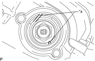
(b) Check that the end of the spring inside of the camshaft timing gear assembly is as shown in the illustration. Text in Illustration
HINT: If the end of the spring is not as shown in the illustration, rotate the crankshaft clockwise 360° and align the timing marks again. |
|
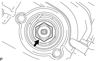
5. REMOVE CAMSHAFT TIMING GEAR BOLT
|
(a) Using SST, hold the crankshaft pulley assembly. SST: 09213-54015 91651-60855 SST: 09330-00021 |
|
.png)
|
(b) Remove the camshaft timing gear bolt. NOTICE: Replace with a new part if it is dropped or if it receives a strong impact. |
|
 Installation
INSTALLATION
PROCEDURE
1. SET NO. 1 CYLINDER TO TDC/COMPRESSION
2. INSTALL CAMSHAFT TIMING GEAR BOLT
NOTICE:
There are different types of camshaft timing gear bolts. Make sure to check the
i ...

Other materials:
Power Source Circuit
DESCRIPTION
This circuit provides power to operate the forward recognition camera.
WIRING DIAGRAM
CAUTION / NOTICE / HINT
NOTICE:
Inspect the fuses for circuits related to this system before performing the following
inspection procedure.
PROCEDURE
1.
CHECK HARNESS A ...
Inspection
INSPECTION
PROCEDURE
1. INSPECT FUEL PUMP
(a) Inspect the resistance of the fuel pump.
(1) Measure the resistance according to the value(s) in the table below.
Text in Illustration
*a
Component without harness connected
(Fuel Pump)
...
A/C ECU Vehicle Information Reading/Writing Processor Malfunction (B15F5)
DESCRIPTION
This DTC is stored when items controlled by the Air conditioning amplifier assembly
cannot be customized via the navigation system vehicle customization screen.
HINT:
The Air conditioning amplifier assembly controls the air conditioning system
related items that are customizable v ...
