Toyota Tacoma (2015-2018) Service Manual: Reassembly
REASSEMBLY
CAUTION / NOTICE / HINT
HINT:
- Use the same procedure for both the LH and RH sides.
- The procedure described below is for the LH side.
PROCEDURE
1. INSTALL CLEARANCE LIGHT BULB
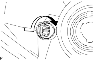
(a) Install the clearance light bulb to the clearance light socket.
|
(b) Turn the clearance light socket with clearance light bulb in the direction indicated by the arrow shown in the illustration to install them. |
|
2. INSTALL FRONT TURN SIGNAL LIGHT BULB
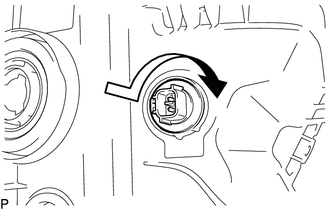
(a) Install the front turn signal light bulb to the front turn signal light socket.
|
(b) Turn the front turn signal light socket with front turn signal light bulb in the direction indicated by the arrow shown in the illustration to install them. |
|
3. INSTALL NO. 2 HEADLIGHT BULB
|
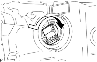
(a) Turn the No. 2 headlight bulb in the direction indicated by the arrow in the illustration to install it. NOTICE: Do not touch the No. 2 headlight bulb glass. |
|
4. INSTALL NO. 1 HEADLIGHT BULB
|
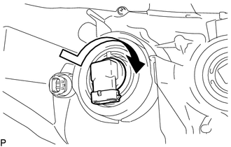
(a) Turn the No. 1 headlight bulb in the direction indicated by the arrow in the illustration to install it. NOTICE: Do not touch the No. 1 headlight bulb glass. |
|
 Installation
INSTALLATION
CAUTION / NOTICE / HINT
HINT:
Use the same procedure for both the LH and RH sides.
The procedure described below is for the LH side.
PROCEDURE
1. INSTALL HEADLIGHT ...
 Headlight Dimmer Relay
Inspection
INSPECTION
PROCEDURE
1. INSPECT HEADLIGHT DIMMER RELAY
(a) Check the resistance.
(1) Measure the resistance according to the value(s) in the table below.
Standard:
...
Other materials:
Maintenance data (fuel, oil level, etc.)
Dimensions
2WD models except PreRunner
*: Unladen vehicle
4WD models and PreRunner (except
Regular Cab models)
*: Unladen vehicle
*: Unladen vehicle
Vehicle capacity weight
2WD models except PreRunner
*: Installing accessories in addition to those installed at the factory increase ...
Adjustment
ADJUSTMENT
CAUTION / NOTICE / HINT
HINT:
Use the same procedures for both the LH and RH sides.
The procedure described below is for the LH side.
Centering bolts are used to mount the door hinge to the vehicle body
and door. The door cannot be adjusted with the centering bolts ...
Certification ECU Communication Stop Mode
DESCRIPTION
Detection Item
Symptom
Trouble Area
Certification ECU Communication Stop Mode
Either condition is met:
Communication stop for "Certification (Smart)" is indicated
on the "Communication Bus Ch ...
