Toyota Tacoma (2015-2018) Service Manual: Removal
REMOVAL
PROCEDURE
1. REMOVE STEERING PAD
(See page .gif) )
)
2. REMOVE STEERING WHEEL ASSEMBLY
3. REMOVE LOWER STEERING COLUMN COVER
4. REMOVE UPPER STEERING COLUMN COVER
5. REMOVE SPIRAL CABLE SUB-ASSEMBLY WITH SENSOR
|
(a) Slide the slider and disconnect the airbag connector. |
|
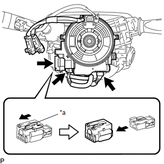
(b) Disconnect the 2 connectors from the spiral cable sub-assembly with sensor.
Text in Illustration|
*a |
Slider |
NOTICE:
When handling the airbag connector, take care not to damage the airbag wire harness.
|
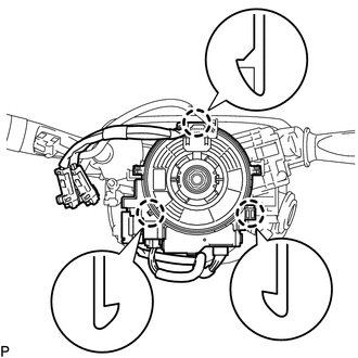
(c) Disengage the 3 claws to remove the spiral cable sub-assembly with sensor. NOTICE:
|
|
 Installation
INSTALLATION
PROCEDURE
1. INSTALL SPIRAL CABLE SUB-ASSEMBLY WITH SENSOR
(a) Check that the ignition switch is off.
(b) Check that the battery n ...
 Traction Off Switch
Components
COMPONENTS
ILLUSTRATION
Removal
REMOVAL
PROCEDURE
1. REMOVE ROOF CONSOLE BOX ASSEMBLY
(See page )
2. REMOVE A-TRAC SWITCH (TRACTION CONTROL SWITCH)
(a) Disconnect the A-TRAC ...
Other materials:
Installation
INSTALLATION
PROCEDURE
1. INSTALL VANE PUMP ASSEMBLY
(a) Install the vane pump assembly with the 2 bolts.
Torque:
21 N·m {214 kgf·cm, 15 ft·lbf}
(b) Connect the ground wire with the bolt.
Torque:
8.5 N·m {87 kgf·cm, 75 in·lbf}
2. CONNECT PRESSURE FEED TUBE ASSEMBLY
(a) Install a ne ...
Front Differential Oil Temperature Sensor Circuit Low (P17C7)
DESCRIPTION
This DTC is output when a short to ground in the oil temperature sensor is detected.
DTC No.
Detection Item
DTC Detection Condition
Trouble Area
P17C7
Front Differential Oil Temperature Sensor Circuit Low
...
Installation
INSTALLATION
CAUTION / NOTICE / HINT
HINT:
Use the same procedure for both the RH and LH sides.
The procedure described below is for the LH side.
PROCEDURE
1. INSTALL SIDE AIRBAG SENSOR ASSEMBLY
(a) Check that the ignition switch is OFF.
(b) Check that the cable is disconnec ...
