Toyota Tacoma (2015-2018) Service Manual: Components
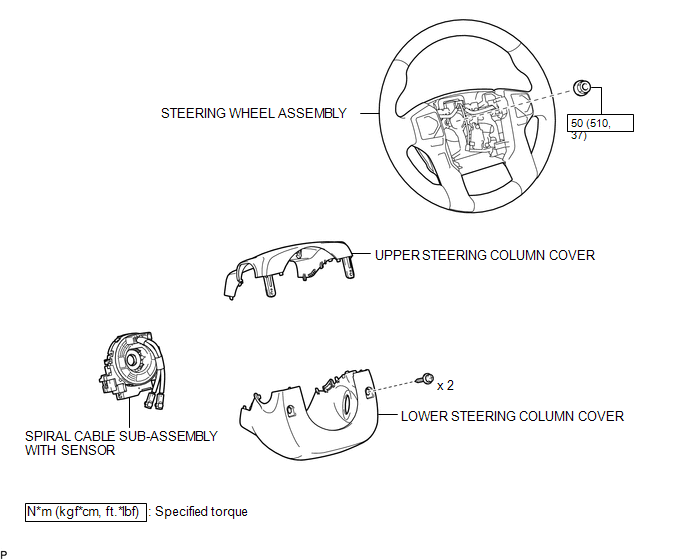
COMPONENTS
ILLUSTRATION

 Installation
INSTALLATION
PROCEDURE
1. INSTALL SPIRAL CABLE SUB-ASSEMBLY WITH SENSOR
(a) Check that the ignition switch is off.
(b) Check that the battery n ...
Other materials:
Installation
INSTALLATION
PROCEDURE
1. INSTALL CLUTCH PEDAL NO.1 CUSHION
(a) Install the clutch pedal No. 1 cushion to the clutch pedal sub-assembly.
2. INSTALL CLUTCH PEDAL SHAFT COLLAR
(a) Apply MP grease to the clutch pedal shaft collar.
Text in Illustration
MP grease
(b) ...
Inspection
INSPECTION
PROCEDURE
1. INSPECT FUEL INJECTOR ASSEMBLY
(a) Measure the resistance according to the value(s) in the table below.
Standard Resistance:
Tester Connection
Condition
Specified Condition
1 - 2
20°C (68°F)
11.6 ...
System Description
SYSTEM DESCRIPTION
1. GENERAL
(a) The blind spot monitor system has the blind spot monitor function and rear
cross traffic alert function.
(1) Blind spot monitor function
The blind spot monitor function is a function that assists the driver
in making the decision to change lanes. Th ...
