Toyota Tacoma (2015-2018) Service Manual: Disassembly
DISASSEMBLY
PROCEDURE
1. REMOVE FRONT LOWER ARM BUSH NO. 1
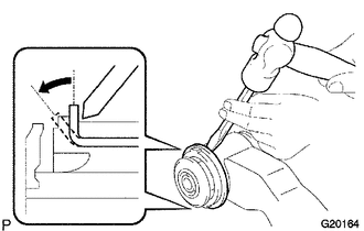
(a) Using a hammer and chisel, raise the flange of the bush diagonally as shown in the illustration.
|
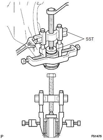
(b) Using SST, remove the lower arm bush. SST: 09950-40011 09951-04010 09952-04010 09953-04020 09954-04010 09955-04011 09957-04010 09958-04011 SST: 09950-60010 09951-00470 |
|
2. REMOVE FRONT LOWER ARM BUSH NO. 2
(a) Using a hammer and chisel, raise the flange of the bush diagonally as shown in the illustration.
|
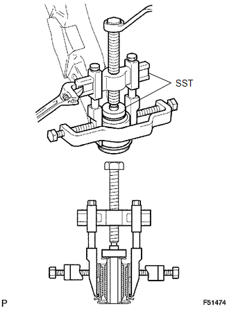
(b) Using SST, remove the lower arm bush. SST: 09950-40011 09951-04010 09952-04010 09953-04020 09954-04010 09955-04011 09957-04010 09958-04011 SST: 09950-60010 09951-00520 |
|
 Components
COMPONENTS
ILLUSTRATION
...
 Removal
REMOVAL
PROCEDURE
1. REMOVE FRONT WHEEL
2. INSPECT FRONT SUSPENSION LOWER ARM
(a) Install the hub nuts onto the disc.
(b) Using a dial indicator, check the lower ball joint for excessive play w ...
Other materials:
Clutch start cancel switch
The switch allows the vehicle to be driven out of difficult situations by cranking
the engine with the clutch engaged.
Never use the switch for normal engine starting. Be sure to follow the starting
procedure.
Press the CLUTCH START CANCEL switch to cancel the clutch start system when the
...
Radio Antenna
Components
COMPONENTS
ILLUSTRATION
Removal
REMOVAL
PROCEDURE
1. REMOVE ROOF HEADLINING ASSEMBLY (for Double Cab)
(See page )
2. REMOVE ROOF HEADLINING ASSEMBLY (for Access Cab)
(See page )
3. REMOVE ANTENNA ASSEMBLY WITH HOLDER
(a) Disengage the 3 clamps.
(b) Remove the nut.
...
Multimedia system types
Entune Audio
Entune Audio Plus
Refer to the ÔÇťNAVIGATION SYSTEM OWNERÔÇÖS MANUALÔÇŁ.
Entune Premium Audio
Refer to the ÔÇťNAVIGATION SYSTEM OWNERÔÇÖS MANUALÔÇŁ.
...
