Toyota Tacoma (2015-2018) Service Manual: Installation
INSTALLATION
PROCEDURE
1. INSTALL WINDSHIELD WIPER MOTOR ASSEMBLY
|
(a) Apply MP grease to the crank arm pivot of the windshield wiper motor assembly. Text in Illustration
|
|
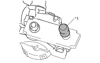
(b) Using a T30 "TORX" socket wrench, install the front wiper motor assembly with the 2 bolts.
Torque:
7.5 N·m {76 kgf·cm, 66 in·lbf}
|
(c) Install the 2 rods to the crank arm pivot of the windshield wiper motor assembly. |
|
2. INSTALL WINDSHIELD WIPER MOTOR AND LINK
|
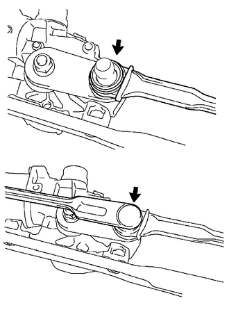
(a) Engage the motor grommet and temporarily install the windshield wiper motor and link as shown in the illustration. Text in Illustration
|
|
(b) Install the windshield wiper motor and link with the 2 bolts.
Torque:
5.5 N·m {56 kgf·cm, 49 in·lbf}
(c) Connect the connector.
3. INSTALL COWL TOP VENTILATOR LOUVER SUB-ASSEMBLY
(a) Engage the 9 guides to install the cowl top ventilator louver sub-assembly.
(b) Engage the guide and 6 claws.
4. INSTALL FRONT FENDER UPPER PROTECTOR LH
(a) Engage the 3 clips to install the front fender upper protector LH.
(b) Install the clip.
5. INSTALL FRONT FENDER UPPER PROTECTOR RH
HINT:
Use the same procedure as for the LH side.
6. INSTALL WINDSHIELD WIPER ARM AND BLADE ASSEMBLY LH
(a) When reusing the windshield wiper arm and blade assembly LH:
|
(1) Clean the wiper arm serrations to remove any burrs, dirt, etc. Text in Illustration
NOTICE: Do not grind down the wiper arm serrations. |
|
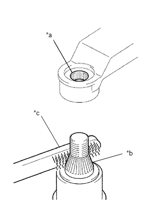
(2) Clean the wiper pivot serrations with a wire brush.
NOTICE:
Do not grind down the wiper pivot serrations.
(3) Operate the front wiper motor and then stop the front wiper motor in the automatic stop (park) position.
|
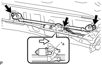
(b) Install the windshield wiper arm and blade assembly LH to the position with the nut as shown in the illustration. Torque: 22 N·m {224 kgf·cm, 16 ft·lbf} Text in Illustration
HINT: Hold the windshield wiper arm and blade assembly LH by hand while tightening the nut. |
|
.png)
(c) Operate the front wipers while spraying washer fluid on the windshield glass. Make sure that the front wipers function properly and there is no interference with the vehicle body.
(d) Check the automatic stop (park) position after lifting the wiper blade 2 times as shown in the illustration.
7. INSTALL WINDSHIELD WIPER ARM AND BLADE ASSEMBLY RH
(a) When reusing the windshield wiper arm and blade assembly RH:
|
(1) Clean the wiper arm serrations to remove any burrs, dirt, etc. Text in Illustration
NOTICE: Do not grind down the wiper arm serrations. |
|
(2) Clean the wiper pivot serrations with a wire brush.
NOTICE:
Do not grind down the wiper pivot serrations.
(3) Operate the front wiper motor and then stop the front wiper motor in the automatic stop (park) position.
|
(b) Install the windshield wiper arm and blade assembly RH to the position with the nut as shown in the illustration. Torque: 22 N·m {224 kgf·cm, 16 ft·lbf} Text in Illustration
HINT: Hold the windshield wiper arm and blade assembly RH by hand while tightening the nut. |
|
.png)
(c) Operate the front wipers while spraying washer fluid on the windshield glass. Make sure that the front wipers function properly and there is no interference with the vehicle body.
(d) Check the automatic stop (park) position after lifting the wiper blade 2 times as shown in the illustration.
8. INSTALL FRONT WIPER ARM HEAD CAP
(a) Engage the 3 claws to install the front wiper arm head cap.
HINT:
Use the same procedure for both sides.
 Inspection
INSPECTION
PROCEDURE
1. INSPECT WINDSHIELD WIPER MOTOR ASSEMBLY
(a) Check the LO operation.
Text in Illustration
*a
Component without harness connected
(Windshield Wipe ...
 Removal
REMOVAL
PROCEDURE
1. REMOVE FRONT WIPER ARM HEAD CAP
(a) Using a screwdriver with its tip wrapped in protective tape, disengage
the 3 claws to remove the front wiper arm head cap.
...
Other materials:
Dtc Check / Clear
DTC CHECK / CLEAR
CHECK DTC
(a) Connect the Techstream to the DLC3.
(b) Turn the ignition switch to ON.
(c) Turn the Techstream on.
(d) Enter the following menus: Chassis / LKA/LDA / Trouble Codes.
(e) Check for DTCs.
Click here
CLEAR DTC
(a) Connect the Techstream to the DLC3.
(b) Turn ...
Components
COMPONENTS
ILLUSTRATION
*1
FORWARD RECOGNITION CAMERA
*2
FORWARD RECOGNITION LATCH
*3
NO. 1 FORWARD RECOGNITION COVER
-
-
...
Front passenger occupant classification system
Your vehicle is equipped with a front passenger occupant classification system.
This system detects the conditions of the right front passenger seat and activates
or deactivates the devices for the front passenger.
1. SRS warning light
2. Front passenger’s seat belt reminder light
3. AIR ...
