Toyota Tacoma (2015-2018) Service Manual: Inspection
INSPECTION
PROCEDURE
1. INSPECT WINDSHIELD WIPER MOTOR ASSEMBLY
(a) Check the LO operation.
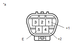
Text in Illustration|
*a |
Component without harness connected (Windshield Wiper Motor Assembly) |
(1) Apply battery voltage to the windshield wiper motor connector and check the speed of the windshield wiper motor assembly.
OK:
|
Measurement Condition |
Specified Condition |
|---|---|
|
Battery positive (+) → Terminal 1 (+1) Battery negative (-) → Terminal 5 (E) |
Motor operates at low speed |
If the result is not as specified, replace the windshield wiper motor assembly.
(b) Check the HI operation.
(1) Apply battery voltage to the windshield wiper motor connector and check the speed of the windshield wiper motor assembly.
OK:
|
Measurement Condition |
Specified Condition |
|---|---|
|
Battery positive (+) → Terminal 4 (+2) Battery negative (-) → Terminal 5 (E) |
Motor operates at high speed |
If the result is not as specified, replace the windshield wiper motor assembly.
 On-vehicle Inspection
ON-VEHICLE INSPECTION
PROCEDURE
1. INSPECT FRONT WIPER MOTOR (for Driver Side)
Text in Illustration
*a
Matchmark
(a) Check the stop (park) position.
(b) Operate t ...
 Installation
INSTALLATION
PROCEDURE
1. INSTALL WINDSHIELD WIPER MOTOR ASSEMBLY
(a) Apply MP grease to the crank arm pivot of the windshield wiper motor
assembly.
Text in Illustration
...
Other materials:
Removal
REMOVAL
PROCEDURE
1. REMOVE SLIDING ROOF SIDE GARNISH LH
(a) Fully open the sunshade trim sub-assembly.
(b) Remove the sliding roof side garnish LH.
2. REMOVE SLIDING ROOF SIDE GARNISH RH
HINT:
Use the same procedure as for the LH side.
3. ...
Rear Differential Lock Position SW Stuck OFF (P17BB)
DESCRIPTION
This DTC is output when an OFF malfunction of the differential lock indicator
switch is detected.
DTC No.
Detection Item
DTC Detection Condition
Trouble Area
P17BB
Rear Differential Lock Position SW Stuck OFF
...
Removal
REMOVAL
PROCEDURE
1. REMOVE FRONT WHEEL
2. REMOVE REAR WHEEL
3. REMOVE TIRE PRESSURE WARNING VALVE AND TRANSMITTER
(a) Remove the cap and valve core to release the air from the tire.
NOTICE:
Keep the removed cap and valve core.
(b) After ensuring that a sufficient amount of air has been rele ...
