Toyota Tacoma (2015-2018) Service Manual: Removal
REMOVAL
PROCEDURE
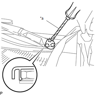
1. REMOVE FRONT WIPER ARM HEAD CAP
|
(a) Using a screwdriver with its tip wrapped in protective tape, disengage the 3 claws to remove the front wiper arm head cap. Text in Illustration
HINT: Use the same procedure for both sides. |
|
2. REMOVE WINDSHIELD WIPER ARM AND BLADE ASSEMBLY LH
|
(a) Remove the nut and windshield wiper arm and blade assembly LH. |
|
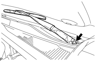
3. REMOVE WINDSHIELD WIPER ARM AND BLADE ASSEMBLY RH
HINT:
Use the same procedure as for the LH side.
4. REMOVE FRONT FENDER UPPER PROTECTOR LH
|
(a) Remove the clip. |
|
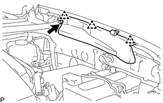
(b) Disengage the 3 clips to remove the front fender upper protector LH.
5. REMOVE FRONT FENDER UPPER PROTECTOR RH
HINT:
Use the same procedure as for the LH side.
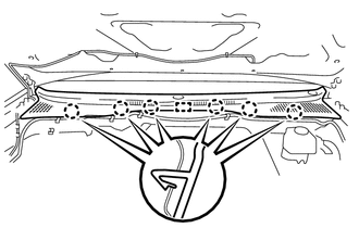
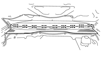
6. REMOVE COWL TOP VENTILATOR LOUVER SUB-ASSEMBLY
|
(a) Disengage the 6 claws and guide. |
|
|
(b) Disengage the 9 guides to remove the cowl top ventilator louver sub-assembly. |
|
7. REMOVE WINDSHIELD WIPER MOTOR AND LINK
|
(a) Disconnect the connector. Text in Illustration
|
|
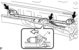
(b) Remove the 2 bolts.
(c) Disengage the motor grommet as shown in the illustration to remove the windshield wiper motor and link.
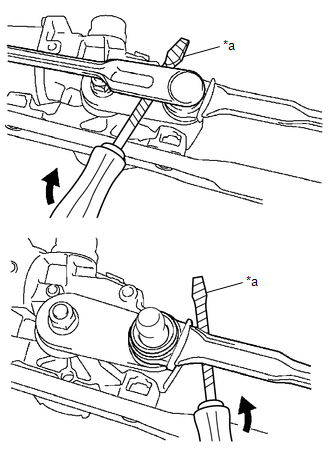
8. REMOVE WINDSHIELD WIPER MOTOR ASSEMBLY
|
(a) Using a screwdriver with its tip wrapped in protective tape, disengage the 2 rods at the crank arm pivot of the windshield wiper motor assembly. Text in Illustration
|
|
|
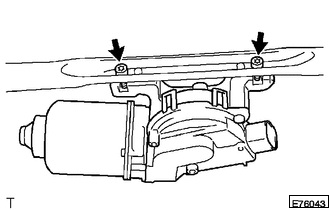
(b) Using a T30 "TORX" socket wrench, remove the 2 bolts and windshield wiper motor assembly. |
|
 Installation
INSTALLATION
PROCEDURE
1. INSTALL WINDSHIELD WIPER MOTOR ASSEMBLY
(a) Apply MP grease to the crank arm pivot of the windshield wiper motor
assembly.
Text in Illustration
...
 Front Wiper Rubber
Components
COMPONENTS
ILLUSTRATION
Installation
INSTALLATION
PROCEDURE
1. INSTALL FRONT WIPER RUBBER
(a) Install the 2 wiper rubber backing plates to the front wiper rubber.
...
Other materials:
Sound Signal Circuit between Radio Receiver and Stereo Jack Adapter
DESCRIPTION
The No. 1 stereo jack adapter assembly sends the sound signal from an external
device to the radio and display receiver assembly via this circuit.
If there is an open or short in the circuit, sound cannot be heard from the speakers
even if there is no malfunction in the radio and d ...
Cleaning and protecting the vehicle interior
The following procedures will help protect your vehicle’s interior and keep
it in top condition:
■ Protecting the vehicle interior
Remove dirt and dust using a vacuum cleaner. Wipe dirty surfaces with a cloth
dampened with lukewarm water.
■ Cleaning the leather areas
● Re ...
Installation
INSTALLATION
PROCEDURE
1. INSTALL AIR CONDITIONING UNIT ASSEMBLY
(a) Temporary install the air conditioning unit assembly.
(b) Insert the bracket hook into the holes of the reinforcement bracket, and
temporary install the instrument panel reinforcement assembly.
(c) Install the instrument p ...
