Toyota Tacoma (2015-2018) Service Manual: Installation
INSTALLATION
CAUTION / NOTICE / HINT
HINT:
- Use the same procedure for both the RH and LH sides.
- The procedure described below is for the LH side.
PROCEDURE
1. INSTALL CURTAIN SHIELD AIRBAG ASSEMBLY
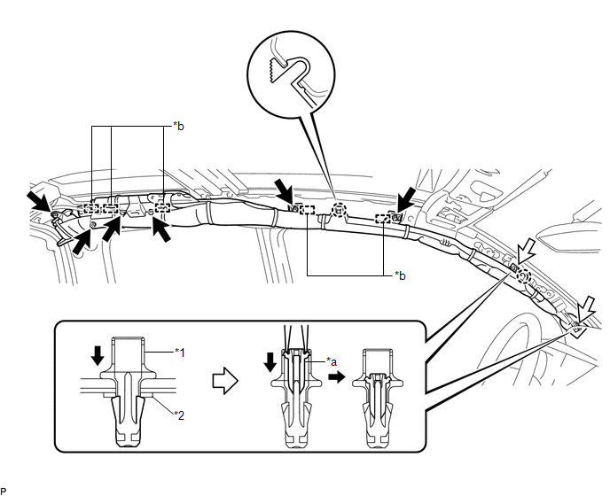
(a) Insert the 5 hooks, install 6 new bolts, 2 new clips with pins and 2 new spacers to install the curtain shield airbag assembly.
 Text in Illustration
|
*1 |
Clip |
*2 |
Spacer |
|
*a |
Pin |
*b |
Hook |
Torque:
12.5 N·m {127 kgf·cm, 9 ft·lbf}
NOTICE:
Do not twist the curtain shield airbag assembly.
|
(b) Connect the connector NOTICE: When handling the airbag connector, take care not to damage the airbag wire harness. |
|
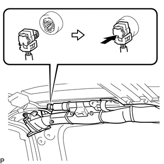
(c) Push in the airbag connector lock to install the airbag connector.
2. INSTALL ROOF HEADLINING ASSEMBLY
Click here .gif)
3. CONNECT CABLE TO NEGATIVE BATTERY TERMINAL
Torque:
5.4 N·m {55 kgf·cm, 48 in·lbf}
NOTICE:
When disconnecting the cable, some systems need to be initialized after the cable is reconnected.
Click here
4. INSPECT SRS WARNING LIGHT
Click here
 Disposal
DISPOSAL
CAUTION / NOTICE / HINT
CAUTION:
Before performing pre-disposal deployment of any SRS part, review and closely
follow all applicable environmental and hazardous material regulations. Pre ...
 Removal
REMOVAL
CAUTION / NOTICE / HINT
HINT:
Use the same procedure for both the RH and LH sides.
The procedure described below is for the LH side.
PROCEDURE
1. PRECAUTION
CAUTION:
B ...
Other materials:
A-TRAC Indicator Light does not Come ON
DESCRIPTION
The A-TRAC does not operate even if the A-TRAC switch is pressed under the following
conditions:
The TRAC or VSC system is faulty.
The temperature inside the hydraulic brake booster increases and the
A-TRAC operation is suspended.
WIRING DIAGRAM
Refer to A-TRAC ...
Accumulator Low Pressure (C1452)
DESCRIPTION
DTC Code
DTC Detection Condition
Trouble Area
C1452
After braking, the fluid pressure inside the accumulator is below the
threshold within 3.2 seconds.
Hydraulic circuit
Accumulator pressure sen ...
Freeze Frame Data
FREEZE FRAME DATA
1. FREEZE FRAME DATA
(a) Whenever a meter DTC is detected, the combination meter assembly stores the
current vehicle state as freeze frame data.
2. CHECK FREEZE FRAME DATA
(a) Connect the Techstream to the DLC3.
(b) Turn the ignition switch to ON.
(c) Turn the Techstream on ...
