Toyota Tacoma (2015-2018) Service Manual: Removal
REMOVAL
CAUTION / NOTICE / HINT
HINT:
- Use the same procedure for both the RH and LH sides.
- The procedure described below is for the LH side.
PROCEDURE
1. PRECAUTION
CAUTION:
Be sure to read Precaution thoroughly before servicing (See page
.gif) ).
).
NOTICE:
After turning the ignition switch off, waiting time may be required before disconnecting the cable from the negative (-) battery terminal. Therefore, make sure to read the disconnecting the cable from the negative (-) battery terminal notices before proceeding with work.
Click here
2. DISCONNECT CABLE FROM NEGATIVE BATTERY TERMINAL
CAUTION:
Wait at least 90 seconds after disconnecting the cable from the negative (-) battery terminal to disable the SRS system.
NOTICE:
When disconnecting the cable, some systems need to be initialized after the cable is reconnected.
Click here
3. REMOVE ROOF HEADLINING ASSEMBLY
Click here
4. REMOVE CURTAIN SHIELD AIRBAG ASSEMBLY
|
(a) Using a screwdriver with its tip wrapped in protective tape, release the airbag connector lock. Text in Illustration
|
|
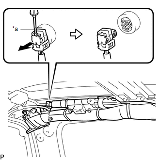
(b) Disconnect the connector.
NOTICE:
When handling the airbag connector, take care not to damage the airbag wire harness.
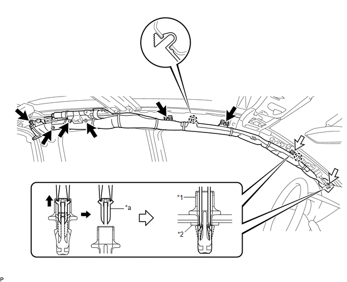
(c) Using needle nose pliers, remove the 2 pins from the 2 clips.
 Text in Illustration
|
*1 |
Clip |
*2 |
Spacer |
|
*a |
Pin |
- |
- |
HINT:
Remove the 2 clips and curtain shield airbag assembly from the vehicle body as a unit.
(d) While holding the curtain shield airbag assembly, remove the 6 bolts, disengage the 2 claws and remove the curtain shield airbag assembly.
(e) Remove the 2 clips and 2 spacers from the curtain shield airbag assembly.
 Installation
INSTALLATION
CAUTION / NOTICE / HINT
HINT:
Use the same procedure for both the RH and LH sides.
The procedure described below is for the LH side.
PROCEDURE
1. INSTALL CURTAIN SH ...

Other materials:
Transponder Key Amplifier
Components
COMPONENTS
ILLUSTRATION
Installation
INSTALLATION
PROCEDURE
1. INSTALL TRANSPONDER KEY COIL
(a) Engage the 2 claws to install the transponder key coil.
(b) Connect the connector.
2. INSTALL UPPER STEERING COLUMN COVER
(S ...
Slip Indicator Light does not Come ON
DESCRIPTION
Refer to Slip Indicator Light Remains ON (See page
).
WIRING DIAGRAM
Refer to Slip Indicator Light Remains ON (See page
).
CAUTION / NOTICE / HINT
NOTICE:
When replacing the skid control ECU (master cylinder solenoid), perform
calibration (See page
).
Inspe ...
Main Owners Manual
Please note that this manual applies to all models explains and all equipment,
including options. Therefore, you may find some explanations for equipment not installed
on your vehicle.
All specifications provided in this manual are current at the time of printing.
However, because of the Toyot ...
