Toyota Tacoma (2015-2018) Service Manual: Engine does not Start
DESCRIPTION
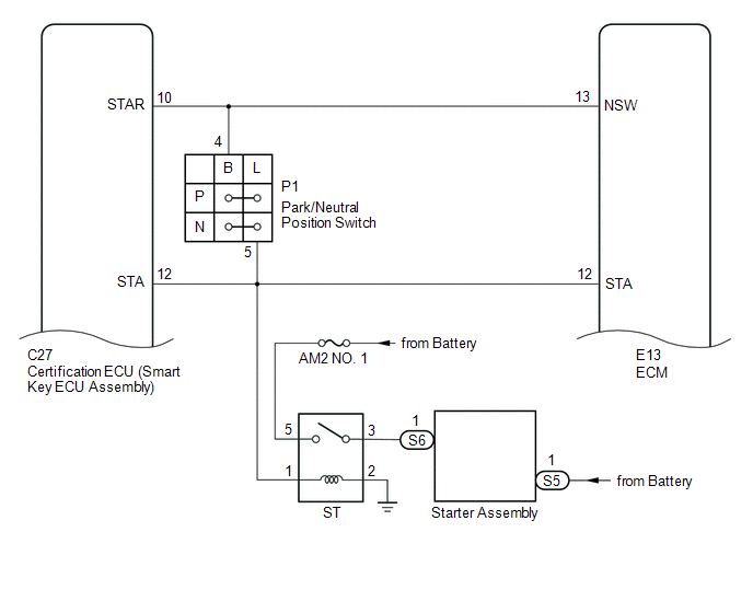
When the key is in the vehicle and the engine switch is pressed, the certification ECU (smart key ECU assembly) receives a signal and changes the power source mode. In addition, when the shift lever is in P or N and the brake pedal is depressed, the engine can be started by pressing the engine switch.
HINT:
- When the certification ECU (smart key ECU assembly) is replaced with a new one and the cable is connected to the negative (-) battery terminal, the power source mode changes to on (IG).
- When the battery cable is disconnected and reconnected, the power source returns to the mode it was in before the battery cable was disconnected.
WIRING DIAGRAM

CAUTION / NOTICE / HINT
NOTICE:
- When using the Techstream with the engine switch off, connect the Techstream to the DLC3 and turn a courtesy light switch on and off at intervals of 1.5 seconds or less until communication between the Techstream and the vehicle begins. Then select the vehicle type under manual mode and enter the following menus: Body Electrical / Smart Key. While using the Techstream, periodically turn a courtesy light switch on and off an intervals of 1.5 seconds or less to maintain communication between the Techstream and the vehicle.
- The smart key system (for Start Function) uses a multiplex communication
system (LIN communication system) and the CAN communication system. Inspect
the communication function by following How to Proceed with Troubleshooting.
Click here
.gif)
Troubleshoot the smart key system (for Start Function) after confirming that the communication systems are functioning properly.
- If the smart key system is disabled through the customize function,
enable the system before performing troubleshooting (See page
).
- Before replacing the certification ECU (smart key ECU assembly) or steering
lock ECU (steering lock actuator or upr bracket assembly), refer to the
smart key system (for Start Function) precaution (See page
).
- Inspect the fuses of circuits related to this system before performing the following inspection procedure.
- If the steering lock ECU (steering lock actuator or upr bracket assembly) is replaced, be sure to confirm that the steering is unlocked by turning the steering wheel to the left and right before starting the engine. If the steering is locked for any reason, open and close a door with the engine switch off, and then unlock the steering by pressing the engine switch. This prevents the engine from starting while the steering is locked.
- After completing repairs, confirm that the problem does not occur.
|
Problem Symptom |
Data List Item |
Active Test Item |
|---|---|---|
|
Engine does not start |
Power Source Control
Smart Key
Starting Control
|
- |
HINT:
If the brake pedal is repeatedly depressed while the engine is stopped, the brake booster pressure is released and the force required to depress the brake pedal to illuminate the stop lights increases.
PROCEDURE
|
1. |
CHECK ELECTRICAL KEY TRANSMITTER SUB-ASSEMBLY |
(a) Press a switch of the electrical key transmitter sub-assembly.
OK:
The electrical key transmitter sub-assembly LED illuminates.
| NG | .gif) |
GO TO STEP 11 |
|
.gif)
|
2. |
READ VALUE USING TECHSTREAM (KEY LOW BATTERY) |
(a) Connect the Techstream to the DLC3.
(b) Turn the engine switch on (IG).
(c) Turn the Techstream on.
(d) Enter the following menus: Body Electrical / Smart Key / Data List.
(e) Read the Data List according to the display on the Techstream.
Smart Key|
Tester Display |
Measurement Item/Range |
Normal Condition |
Diagnostic Note |
|---|---|---|---|
|
Key Low Battery |
Transmitter battery depleted/Yes or No |
YES: Transmitter battery depleted NO: Transmitter battery not depleted |
The electrical key transmitter sub-assembly sends voltage information to the certification ECU (smart key ECU assembly) when it is transmitting. The certification ECU (smart key ECU assembly) displays "YES" for the "Key Low Battery" item of the Data List when this voltage information indicates 2.2 V or less. This Data List item should be checked when the electrical key transmitter sub-assembly is at room temperature (example: at -20°C (-4°F), "YES" may be displayed even if the transmitter battery is new). |
|
Result |
Proceed to |
|---|---|
|
"NO" is displayed on the Techstream screen |
A |
|
"YES" is displayed on the Techstream screen |
B |
| B | |
REPLACE TRANSMITTER BATTERY |
|
|
3. |
CHECK WAVE ENVIRONMENT |
(a) If the problem occurs in certain locations or times of day, the possibility of wave interference is high.
HINT:
Whether the problem is due to wave interference can be checked by holding the electrical key transmitter sub-assembly near the electrical key and TPMS receiver assembly.
OK:
Engine starts.
Result|
Result |
Proceed to |
|---|---|
|
NG |
A |
|
OK |
B |
| B | |
AFFECTED BY WAVE INTERFERENCE |
|
|
4. |
CHECK ENGINE SWITCH CONDITION |
(a) Get into the vehicle while carrying an electrical key transmitter sub-assembly.
(b) Move the shift lever to P.
(c) With the brake pedal released, check that pressing the engine switch causes the power source mode to change.
Result|
Result |
Proceed to |
|---|---|
|
Power source mode changes: Off → on (ACC) → on (IG) → off |
A |
|
Power source mode does not change to on (ACC) or on (IG) |
B |
|
Power source mode changes to on (IG) but not to on (ACC) |
C |
|
Power source mode changes to on (ACC) but not to on (IG) |
D |
| B | |
GO TO POWER SOURCE MODE DOES NOT CHANGE TO ON (IG AND ACC) |
| C | |
GO TO POWER SOURCE MODE DOES NOT CHANGE TO ON (ACC) |
| D | |
GO TO POWER SOURCE MODE DOES NOT CHANGE TO ON (IG) |
|
|
5. |
READ VALUE USING TECHSTREAM (NEUTRAL SW / CLUTCH SW, SHIFT POSITION P OR N) |
(a) Connect the Techstream to the DLC3.
(b) Turn the engine switch on (IG).
(c) Turn the Techstream on.
(d) Enter the following menus: Body Electrical / Power Source Control or Starting Control / Data List.
(e) Read the Data List according to the display on the Techstream.
Power Source Control|
Tester Display |
Measurement Item/Range |
Normal Condition |
Diagnostic Note |
|---|---|---|---|
|
Neutral SW/ Clutch SW |
Shift position (P and N)/ON or OFF |
ON: Shift lever in P or N OFF: Shift lever in any position other than P or N |
|
|
Tester Display |
Measurement Item/Range |
Normal Condition |
Diagnostic Note |
|---|---|---|---|
|
Shift Position P or N |
Park/neutral position switch status/ON or OFF |
ON: Shift lever in P OFF: Shift lever not in P |
When malfunctioning, the engine will not crank. |
OK:
The Techstream display changes correctly in response to the shift position.
| NG | |
GO TO STEP 23 |
|
|
6. |
CHECK FOR DTC |
(a) Using the Techstream, check for certification ECU (smart key ECU assembly)
DTCs (See page ).
|
Result |
Proceed to |
|---|---|
|
DTCs are not output |
A |
|
Smart key system (for Start Function) DTCs are output |
B |
| B | |
GO TO DIAGNOSTIC TROUBLE CODE CHART |
|
|
7. |
READ VALUE USING TECHSTREAM (STOP LIGHT SWITCH1) |
(a) Connect the Techstream to the DLC3.
(b) Turn the engine switch on (IG).
(c) Turn the Techstream on.
(d) Enter the following menus: Body Electrical / Power Source Control / Data List.
(e) Read the Data List according to the display on the Techstream.
Power Source Control|
Tester Display |
Measurement Item/Range |
Normal Condition |
Diagnostic Note |
|---|---|---|---|
|
Stop Light Switch1 |
State of brake pedal/ON or OFF |
ON: Brake pedal depressed OFF: Brake pedal released |
|
OK:
The Techstream display changes correctly in response to the brake operation.
| NG | |
GO TO STEP 21 |
|
|
8. |
READ VALUE USING TECHSTREAM (STARTER REQUEST SIGNAL) |
(a) Connect the Techstream to the DLC3.
(b) Turn the engine switch on (IG).
(c) Turn the Techstream on.
(d) Enter the following menus: Body Electrical / Power Source Control / Data List.
(e) Read the Data List according to the display on the Techstream.
Power Source Control|
Tester Display |
Measurement Item/Range |
Normal Condition |
Diagnostic Note |
|---|---|---|---|
|
Starter Request Signal |
Engine start request signal status/ON or OFF |
ON: With the shift lever in P and the brake pedal depressed, the engine switch is pressed and held OFF: After approx. 1 second has elapsed, the engine switch is released |
|
NOTICE:
Check that the key indicator is displayed on the multi-information display in the combination meter assembly, and then press the engine switch.
OK:
The Techstream display changes correctly in response to the engine switch operation.
| NG | |
GO TO STEP 12 |
|
|
9. |
CHECK STEERING LOCK |
(a) Check that the steering unlocks when the engine switch is turned on (ACC).
OK:
The steering unlocks.
| NG | |
GO TO STEERING LOCK SYSTEM (UNABLE TO UNLOCK STEERING) |
|
|
10. |
CHECK SECURITY INDICATOR LIGHT (IMMOBILISER SYSTEM UNSET) |
(a) Get into the vehicle while carrying an electrical key transmitter sub-assembly.
(b) Move the shift lever to P.
(c) Press the engine switch with the brake pedal released and check that the security indicator light changes from blinking to off at the same time that the power source mode changes to on (ACC).
HINT:
The immobiliser function can be determined to be operating correctly if the security indicator light changes from blinking to off at the same time that the power source mode changes to on (ACC).
OK:
The security indicator light changes from blinking to off at the same time that power source mode changes to on (ACC).
| OK | |
REPLACE CERTIFICATION ECU (SMART KEY ECU ASSEMBLY) |
| NG | |
GO TO IMMOBILISER SYSTEM (PROBLEM SYMPTOMS TABLE) |
|
11. |
INSPECT TRANSMITTER BATTERY |
(a) Inspect the transmitter battery (See page
).
NOTICE:
Do not wrap the lead wire around a terminal, wedge it between terminals, or solder it. The terminal may be deformed or damaged, and the transmitter battery will not be able to be installed correctly.
| OK | |
REPLACE ELECTRICAL KEY TRANSMITTER SUB-ASSEMBLY |
| NG | |
REPLACE TRANSMITTER BATTERY |
|
12. |
READ VALUE USING TECHSTREAM (STARTER SW) |
(a) Connect the Techstream to the DLC3.
(b) Turn the engine switch on (IG).
(c) Turn the Techstream on.
(d) Enter the following menus: Body Electrical / Starting Control / Data List.
(e) Read the Data List according to the display on the Techstream.
(f) Get into the vehicle while carrying the electrical key transmitter sub-assembly, move the shift lever to P, press the engine switch while depressing the brake pedal and confirm that the Techstream display changes.
Starting Control|
Tester Display |
Measurement Item/Range |
Normal Condition |
Diagnostic Note |
|---|---|---|---|
|
Starter SW |
Starter operation request/ON or OFF |
ON: Starter operation requested OFF: Starter operation not requested |
When malfunctioning, the engine will not crank. |
OK:
The Techstream display changes.
| NG | |
REPLACE CERTIFICATION ECU (SMART KEY ECU ASSEMBLY) |
|
|
13. |
INSPECT ST RELAY (STARTER RELAY ASSEMBLY) |
(a) Inspect the ST relay (starter relay assembly) (See page
).
| NG | |
REPLACE ST RELAY (STARTER RELAY ASSEMBLY) |
|
|
14. |
CHECK HARNESS AND CONNECTOR (CERTIFICATION ECU (SMART KEY ECU ASSEMBLY) - BODY GROUND) |
|
(a) Disconnect the C27 certification ECU (smart key ECU assembly) connector. |
|
(b) Disconnect the E13 ECM connector.
(c) Move the shift lever to P or N.
(d) Measure the resistance according to the value(s) in the table below.
Standard Resistance:
|
Tester Connection |
Condition |
Specified Condition |
|---|---|---|
|
C27-10 (STAR) - Body ground |
20°C (68°F) |
107.05 to 116.33 Ω |
|
C27-12 (STA) - Body ground |
20°C (68°F) |
106.78 to 115.98 Ω |
|
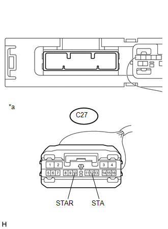
*a |
Front view of wire harness connector (to Certification ECU (Smart Key ECU Assembly)) |
| NG | |
GO TO STEP 17 |
|
|
15. |
INSPECT STARTER ASSEMBLY |
(a) Remove the starter assembly (See page
).
(b) Inspect the starter assembly (See page ).
| NG | |
REPLACE STARTER ASSEMBLY |
|
|
16. |
CHECK HARNESS AND CONNECTOR (BATTERY - STARTER ASSEMBLY AND ST RELAY (STARTER RELAY ASSEMBLY)) |
(a) Disconnect the S5 and S6 starter assembly connectors.
(b) Remove the ST relay (starter relay assembly) from the engine room relay block assembly.
|
(c) Measure the voltage according to the value(s) in the table below. Standard Voltage:
|
|
(d) Measure the resistance according to the value(s) in the table below.
Standard Resistance:
|
Tester Connection |
Condition |
Specified Condition |
|---|---|---|
|
3 (ST relay (starter relay assembly)) - S6-1 |
Always |
Below 1 Ω |
|
3 (ST relay (starter relay assembly)) or S6-1 - Body ground |
Always |
10 kΩ or higher |
|
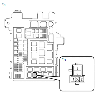
*a |
Engine Room Relay Block |
|
*b |
ST Relay (Starter Relay Assembly) Holder |
| OK | |
USE SIMULATION METHOD TO CHECK |
| NG | |
REPAIR OR REPLACE HARNESS OR CONNECTOR |
|
17. |
CHECK HARNESS AND CONNECTOR (CERTIFICATION ECU (SMART KEY ECU ASSEMBLY) - PARK/NEUTRAL POSITION SWITCH) |
(a) Disconnect the C27 certification ECU (smart key ECU assembly) connector.
(b) Disconnect the P1 park/neutral position switch connector.
(c) Disconnect the E13 ECM connector.
(d) Measure the resistance according to the value(s) in the table below.
Standard Resistance:
|
Tester Connection |
Condition |
Specified Condition |
|---|---|---|
|
C27-10 (STAR) - P1-4 (B) |
Always |
Below 1 Ω |
|
C27-10 (STAR) or P1-4 (B) - Body ground |
Always |
10 kΩ or higher |
| NG | |
REPAIR OR REPLACE HARNESS OR CONNECTOR |
|
|
18. |
CHECK HARNESS AND CONNECTOR (PARK/NEUTRAL POSITION SWITCH - ST RELAY (STARTER RELAY ASSEMBLY)) |
(a) Disconnect the P1 park/neutral position switch connector.
(b) Remove the ST relay (starter relay assembly) from the engine room relay block assembly.
(c) Disconnect the E13 ECM connector.
(d) Disconnect the C27 certification ECU (smart key ECU assembly) connector.
(e) Measure the resistance according to the value(s) in the table below.
Standard Resistance:
|
Tester Connection |
Condition |
Specified Condition |
|---|---|---|
|
P1-5 (L) - 1 (ST relay (starter relay assembly)) |
Always |
Below 1 Ω |
|
P1-5 (L) or 1 (ST relay (starter relay assembly)) - Body ground |
Always |
10 kΩ or higher |
| NG | |
REPAIR OR REPLACE HARNESS OR CONNECTOR |
|
|
19. |
CHECK HARNESS AND CONNECTOR (CERTIFICATION ECU (SMART KEY ECU ASSEMBLY) - ST RELAY (STARTER RELAY ASSEMBLY)) |
(a) Disconnect the C27 certification ECU (smart key ECU assembly) connector.
(b) Remove the ST relay (starter relay assembly) from the engine room relay block assembly.
(c) Disconnect the E13 ECM connector.
(d) Disconnect the P1 park/neutral position switch connector.
(e) Measure the resistance according to the value(s) in the table below.
Standard Resistance:
|
Tester Connection |
Condition |
Specified Condition |
|---|---|---|
|
C27-12 (STA) - 1 (ST relay (starter relay assembly)) |
Always |
Below 1 Ω |
|
C27-12 (STA) or 1 (ST relay (starter relay assembly)) - Body ground |
Always |
10 kΩ or higher |
| NG | |
REPAIR OR REPLACE HARNESS OR CONNECTOR |
|
|
20. |
CHECK HARNESS AND CONNECTOR (ST RELAY (STARTER RELAY ASSEMBLY - BODY GROUND)) |
(a) Remove the ST relay (starter relay assembly) from the engine room relay block assembly.
(b) Measure the resistance according to the value(s) in the table below.
Standard Resistance:
|
Tester Connection |
Condition |
Specified Condition |
|---|---|---|
|
1 (ST relay (starter relay assembly)) - Body ground |
Always |
Below 1 Ω |
| OK | |
USE SIMULATION METHOD TO CHECK |
| NG | |
REPAIR OR REPLACE HARNESS OR CONNECTOR |
|
21. |
CHECK HARNESS AND CONNECTOR (CERTIFICATION ECU (SMART KEY ECU ASSEMBLY) - STOP LIGHT SWITCH ASSEMBLY) |
(a) Disconnect the C27 certification ECU (smart key ECU assembly) connector.
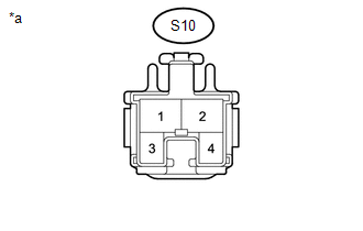
(b) Disconnect the S10 stop light switch assembly connector.
(c) Disconnect the E13 ECM connector.
(d) Disconnect the S7 transmission floor shift assembly connector.
(e) Disconnect the S1 skid control ECU (brake actuator assembly) connector.
(f) Disconnect the R38 rear combination light assembly LH connector.
(g) Disconnect the R39 rear combination light assembly RH connector.
(h) Disconnect the C15 center stop light assembly connector.
|
(i) Measure the voltage according to the value(s) in the table below. Standard Voltage:
|
|
(j) Measure the resistance according to the value(s) in the table below.
Standard Resistance:
|
Tester Connection |
Condition |
Specified Condition |
|---|---|---|
|
C27-2 (STP1) - S10-1 |
Always |
Below 1 Ω |
|
C27-2 (STP1) or S10-1 - Body ground |
Always |
10 kΩ or higher |
| NG | |
REPAIR OR REPLACE HARNESS OR CONNECTOR |
|
|
22. |
INSPECT STOP LIGHT SWITCH ASSEMBLY |
(a) Inspect the stop light switch assembly (See page
).
| OK | |
REPLACE CERTIFICATION ECU (SMART KEY ECU ASSEMBLY) |
| NG | |
REPLACE STOP LIGHT SWITCH ASSEMBLY |
|
23. |
INSPECT PARK/NEUTRAL POSITION SWITCH |
(a) Remove the park/neutral position switch.
for AC60E: (See page )
for AC60F: (See page )
(b) Inspect the park/neutral position switch.
for AC60E: (See page )
for AC60F: (See page )
|
Result |
Proceed to |
|---|---|
|
OK |
A |
|
NG (for AC60E) |
B |
|
NG (for AC60F) |
C |
| B | |
REPLACE PARK/NEUTRAL POSITION SWITCH |
| C | |
REPLACE PARK/NEUTRAL POSITION SWITCH |
|
|
24. |
CHECK HARNESS AND CONNECTOR (CERTIFICATION ECU (SMART KEY ECU ASSEMBLY) - PARK/NEUTRAL POSITION SWITCH)) |
(a) Disconnect the C27 certification ECU (smart key ECU assembly) connector.
(b) Disconnect the P1 park/neutral position switch connector.
(c) Disconnect the E13 ECM connector.
(d) Remove the ST relay (starter relay assembly) from the engine room relay block assembly.
(e) Measure the resistance according to the value(s) in the table below.
Standard Resistance:
|
Tester Connection |
Condition |
Specified Condition |
|---|---|---|
|
C27-10 (STAR) - P1-4 (B) |
Always |
Below 1 Ω |
|
C27-10 (STAR) or P1-4 (B) - Body ground |
Always |
10 kΩ or higher |
| OK | |
REPLACE CERTIFICATION ECU (SMART KEY ECU ASSEMBLY) |
| NG | |
REPAIR OR REPLACE HARNESS OR CONNECTOR |
 ACC Monitor Malfunction (B2274)
DESCRIPTION
This DTC is stored when a malfunction in the ACC output circuit is detected.
The ACC output circuit is the circuit that goes from the ACC output terminal of
the certification ECU (sma ...
 Power Source Mode does not Change to ON (IG and ACC)
DESCRIPTION
If any of the following operations are performed, the certification ECU (smart
key ECU assembly) receives a signal, and changes the power source mode.
With the electrical key tr ...
Other materials:
Removal
REMOVAL
PROCEDURE
1. REMOVE NO. 2 ENGINE UNDER COVER SUB-ASSEMBLY (w/ Off Road Package)
2. REMOVE NO. 1 ENGINE UNDER COVER SUB-ASSEMBLY
3. DRAIN ENGINE COOLANT
4. REMOVE RADIATOR GRILLE
(See page )
5. REMOVE V-BANK COVER SUB-ASSEMBLY
6. REMOVE RADIATOR SUPPORT TO FRAME SEAL
7. R ...
Check Mode Procedure
CHECK MODE PROCEDURE
1. DESCRIPTION
Check mode has a higher sensitivity to malfunctions and can detect malfunctions
that cannot be detected in normal mode. Check mode can also detect all of the malfunctions
that can be detected in normal mode. In check mode, DTCs are stored with 1 trip
detec ...
Cruise Control Switch Circuit
DESCRIPTION
The cruise control main switch is used to turn the dynamic radar cruise control
system on and off, as well as operate 7 functions: SET, - (COAST), TAP-DOWN, RES
(RESUME), + (ACCEL), TAP-UP and CANCEL.
The SET, TAP-DOWN and - (COAST) functions, and the RES (RESUME), TAP-UP and +
( ...
