Toyota Tacoma (2015-2018) Service Manual: Components
COMPONENTS
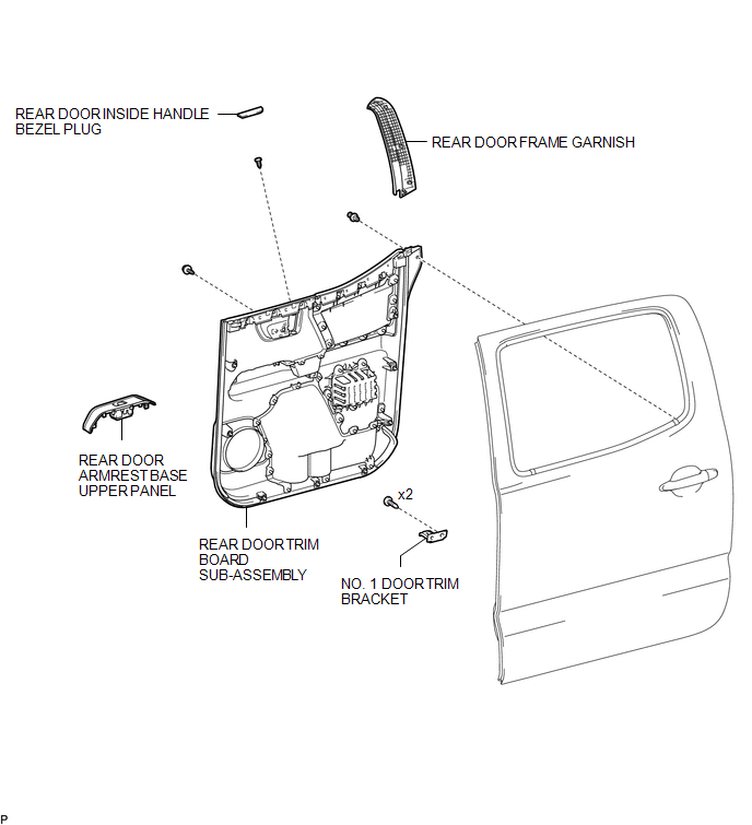
ILLUSTRATION
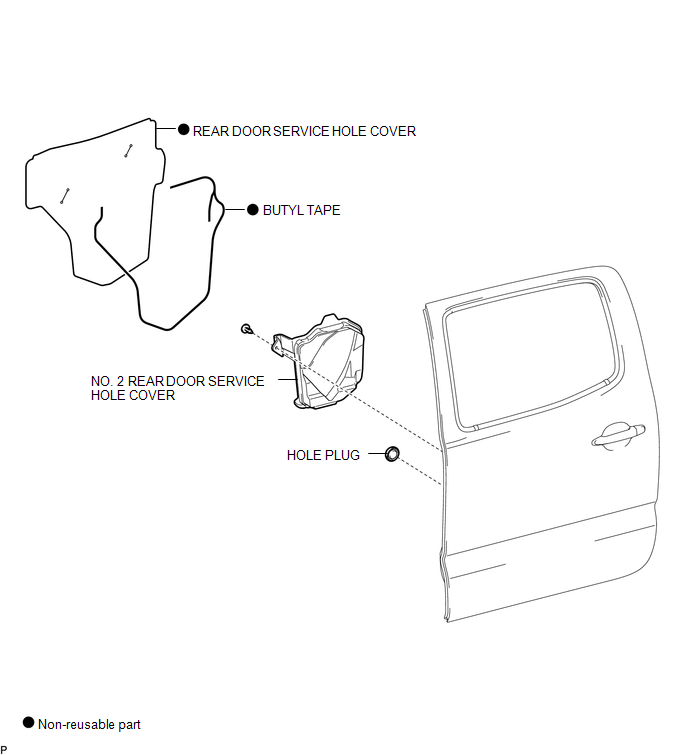
ILLUSTRATION
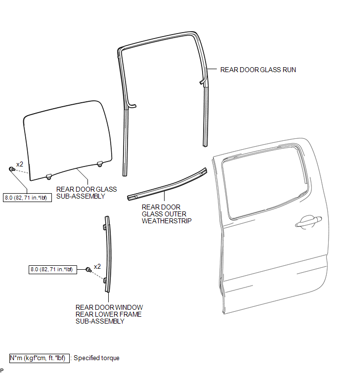
ILLUSTRATION

 Installation
INSTALLATION
CAUTION / NOTICE / HINT
HINT:
Use the same procedure for the RH side and LH side.
The following procedure is for the LH side.
PROCEDURE
1. INSTALL REAR DOOR GLASS O ...
Other materials:
USB port/AUX port
Connect an iPod, USB memory device or portable audio player to the USB port/AUX
port as indicated below. Select “iPod”, “USB” or “AUX” on the “Select Audio Source”
screen and the device can be operated via multimedia system.
Connecting using the USB port/AUX port
■ iPod
...
Terminals Of Ecu
TERMINALS OF ECU
CHECK ECM
HINT:
The standard voltage, resistance and waveform between each pair of the ECM terminals
is shown in the table below. The appropriate conditions for checking each pair of
the terminals is also indicated. The result of checks should be compared with the
standar ...
IG Signal Circuit
DESCRIPTION
This circuit detects whether the ignition switch is ON or off, and sends this
information to the main body ECU (multiplex network body ECU).
WIRING DIAGRAM
CAUTION / NOTICE / HINT
NOTICE:
Inspect the fuses for circuits related to this system before performing
the fol ...
